In basic optics, light is usually described as traveling in straight lines within uniform media, undergoing phenomena such as refraction, reflection, or total internal reflection when entering different media. While this geometric description is valid for engineering calculations, we should consider a fundamental question: where exactly does light’s propagation behavior change?
From the perspective of propagation, light is a stable electromagnetic process within a uniform medium, and its direction does not change spontaneously. The change in propagation state does not happen due to evolution within the medium, but at the exact moment light reaches the boundary of the medium.
The interface can change the light’s behavior because it connects two media with different refractive indices, forcing the electromagnetic wave to satisfy two different sets of boundary conditions simultaneously. Under this constraint, light propagation is no longer a continuous process within a single medium; it becomes a process where propagation conditions are rematched and reconstructed.
Therefore, the path of light is not gradually curved in space. Instead, different interface conditions correspond to different output branches. For example, light may transmit into a new medium and change direction (refraction), reflect into the original medium (reflection), or be unable to enter the second medium under specific conditions (total internal reflection). From this perspective, within the same structure, refraction, reflection, and total internal reflection are not three independent phenomena, but three propagation modes of the same interface mechanism under different boundary conditions.
Fundamental Results of Light Propagation at Interfaces
When light encounters any medium interface, its behavior is determined by the conditions that electromagnetic waves must satisfy at that interface. Based on this unified constraint, all possible results for light at an interface can essentially be summarized into two categories: reflection and transmission. Under different boundary conditions, transmission further manifests as refraction (normal propagation) or restricted propagation under total internal reflection conditions.
Reflexion
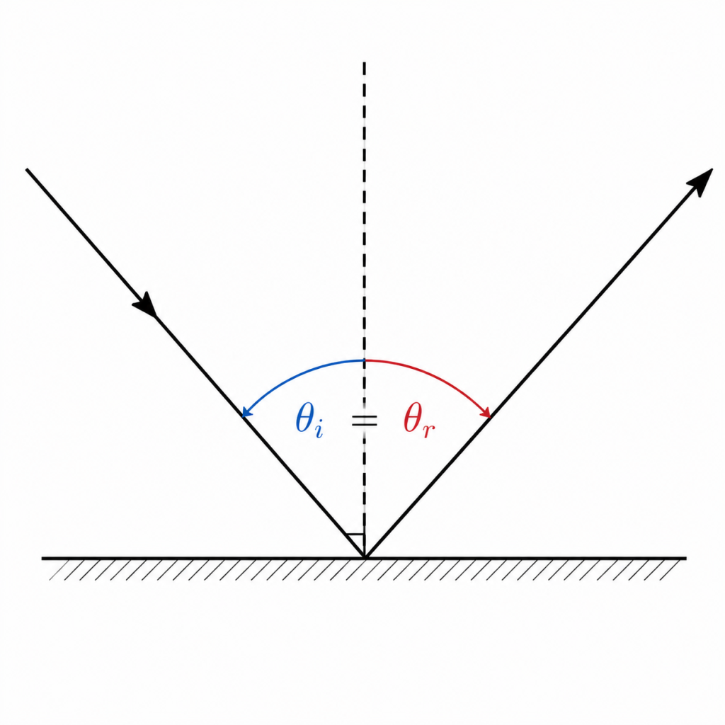
Reflection is the phenomenon where light returns to the original medium after reaching an interface. In this process, the direction of light propagation changes, but the medium remains the same.
Physically, reflection occurs because when an electromagnetic wave reaches an interface, the electric and magnetic fields must simultaneously satisfy continuity conditions. If the incident wave cannot establish a complete corresponding propagation solution in the second medium, the system must generate a backward-propagating wave to maintain the overall boundary conditions.
(1)Physical Mechanism
From electromagnetic theory, the key issue at the interface is how to satisfy field continuity between two media with different electromagnetic parameters. Because the refractive indices of the two media differ, the incident wave cannot form a solution that fully satisfies the boundary conditions in the second medium alone. Therefore, the system automatically splits into two coupled solutions:
- A solution entering the second medium (transmitted solution)
- A solution returning to the original medium (reflected solution)
These two solutions together ensure the overall self-consistency of the electromagnetic field at the interface. You can understand this more strictly as: reflection is not energy bouncing back, but the result of completing the full solution space under the constraint of boundary conditions.
(2)Classification
Reflection does not take a single form in real-world systems; it is determined by the interface structure and microscopic morphology. It mainly includes the following types:
- Specular Reflection: Occurs when the interface is sufficiently smooth and structurally uniform. In this case, the phase relationship of the incident wave remains consistent on a macroscopic scale, so the reflection direction follows clear geometric rules.
- Diffuse Reflection: Originates from the irregularity of the surface microstructure. Incident light produces different phase and direction scattering overlays in different small regions, causing the reflected energy to be diffused in space.
- Partial Reflection: This is the most common state, indicating that the interface possesses both effective reflection and transmission solution structures. Energy is naturally distributed between them according to boundary conditions.
(3)Characteristics
An important characteristic of reflection is its universality. As long as a medium interface exists and satisfies the constraints of electromagnetic boundary conditions, reflection will occur, regardless of whether the medium is transparent or the specific material combination.
In this sense, reflection is not a unique property of certain materials, but a fundamental result of electromagnetic interaction at an interface.
The strength of reflection is expressed as “reflectivity.” This is not a fixed value but a variable that changes continuously with system conditions. Specifically, reflectivity is determined by the difference in refractive indices, the angle of incidence, and the polarization state of the light. Therefore, it can vary continuously from nearly 0 (almost total transmission) to nearly 1 (almost total reflection) under different conditions.
(4)Engineering Issues
In optical engineering systems, reflection is both a core design tool and a system factor that requires strict control. On one hand, reflection is widely used for optical path control and direction modulation, such as in mirror systems, folded optical paths, and laser resonant cavities. By using multiple reflections, one can constrain beam paths and achieve energy feedback, thereby redirecting light or enhancing the optical field.
On the other hand, if reflection is not effectively controlled, it can lead to a series of practical engineering problems. The most common is energy loss, such as non-ideal reflection or absorption at an interface, which reduces the transmitted light intensity. Secondly, there is the problem of stray light, which originates from surface microscopic roughness or contamination, causing light energy to scatter and diffuse. In multi-interface optical systems, multiple unintended reflections may occur, causing path deviations, ghost images, and noise, which reduce system imaging precision or signal stability.
Therefore, in precision optische Gestaltung, reflection is not just a simple phenomenon but an interface effect parameter that must be quantitatively designed and controlled.
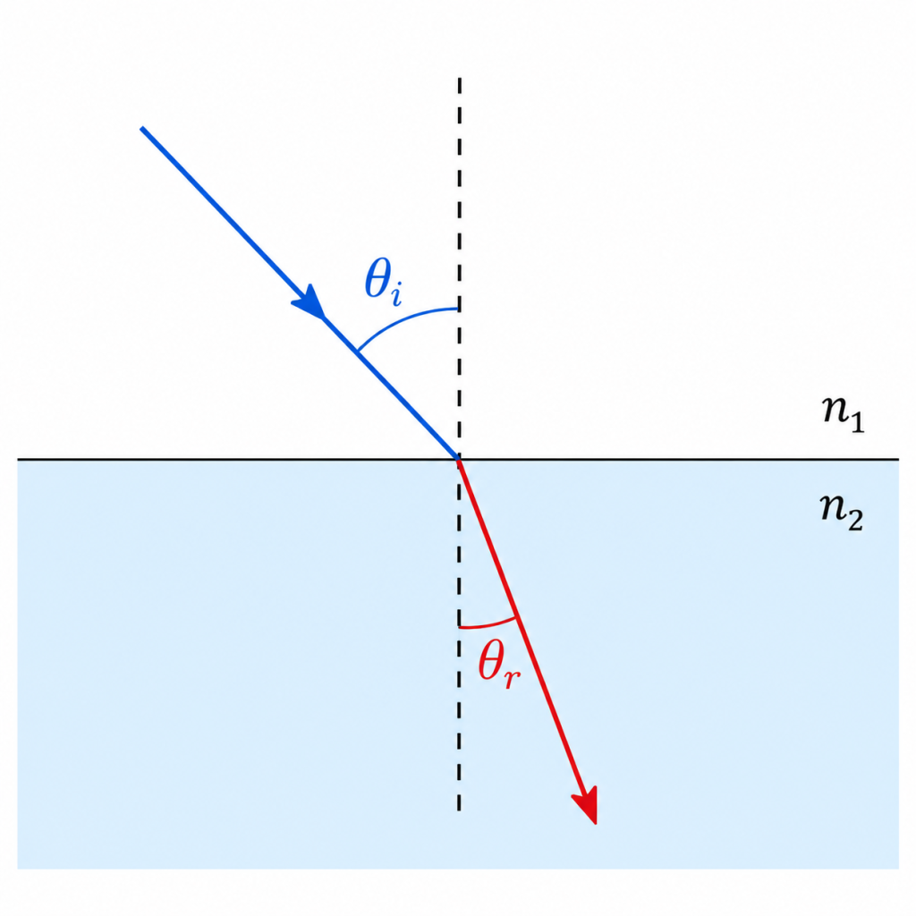
Brechung
Refraction occurs when light crosses between two media with different refractive indices. At this point, light not only changes its propagation direction, but its speed also changes according to the medium.
A more thorough understanding is that refraction comes from the inconsistency of the wavefront propagation speed in different media. When part of the wavefront travels faster or slower in a certain area, the entire wavefront tilts and rearranges. This spatial reconstruction ultimately manifests as the deflection of the light ray direction.
(1)Physical Mechanism
The essential cause of refraction is that light travels at different speeds in different media. When light enters a new medium from another, the part that enters earlier changes speed first, while the part that has not yet entered continues at the original speed. Because different parts of the same wavefront have inconsistent speeds, the entire wavefront no longer maintains its original direction and undergoes gradual shape changes.
When light enters a new medium, because light propagates as a wave, different positions of the same wavefront enter the new medium at different times:
- The part that enters the new medium first: Experiences the new propagation speed earlier (faster or slower).
- The part still in the original medium: Continues at the original propagation speed.
This speed difference causes an adjustment in the overall direction, ultimately manifesting as a change in propagation direction, which is the phenomenon of refraction.
(2)Control Parameters
The core control factor for refraction is the difference in refractive indices, which determines the magnitude of the change in light speed on both sides of the interface and is therefore the fundamental parameter affecting the degree of light deflection.
When the incident angle is small, light mainly enters the second medium along the normal line, resulting in weak deflection. When the incident angle increases, the interface effect strengthens, and the change in the refraction angle becomes more obvious. Therefore, the angle of incidence can be understood as a geometric condition that adjusts the intensity of the refraction response.
Wellenlänge affects the material’s response to different light, because the refractive index of actual materials is not a fixed value but changes with wavelength. This means that different colors of light will experience slightly different propagation speeds in the same medium, resulting in different refraction angles.
When this wavelength dependence is significant, the phenomenon of different colors of light separating, known as dispersion, occurs. For example, white light passing through a prism and being broken down into multiple colors is caused by different wavelengths corresponding to different refractive indices.
(3)Application Issues
In applications, the main issues with refractive systems focus on material limitations and chromatic aberration control. First, because different wavelengths travel at different speeds in the same material, a single-material lens cannot achieve the same focal position for all colors of light. This means different wavelengths will focus at different points in space, leading to blurred edges or colored fringes in imaging. Therefore, it is usually necessary to use a combination of two or more materials (such as Achromatische Linse structures) to cancel out these differences so that different wavelengths focus at the same position as much as possible.
Secondly, in high-precision imaging or Lasersysteme, even small refractive errors can be amplified. This is because optical systems usually contain multiple lenses or long propagation paths; tiny angular deviations will gradually accumulate over the distance, eventually manifesting as focal shifts, beam divergence, or imaging position drift.
Interne Gesamtreflexion
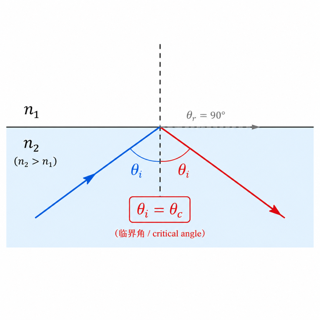
Interne Totalreflexion occurs when light travels from a high-refractive-index medium to a low-refractive-index medium, and the angle of incidence is greater than the critical angle. Under these conditions, light cannot form an effective propagation solution in the second medium, so no energy transmission occurs.
Mechanistically, the key to this phenomenon is not enhanced reflection but the disappearance of the transmission channel. When boundary conditions no longer allow a propagation solution to exist, the electromagnetic wave cannot enter the second medium and can only exist as a reflection in the original medium, creating a totally returned energy distribution.
(1)Occurrence Conditions
The occurrence of total internal reflection requires two conditions to be met simultaneously: first, light must enter a low-refractive-index medium from a high-refractive-index medium, and second, the angle of incidence must be greater than the critical angle. These two conditions essentially determine a key question: whether the transmitted light can still exist as a propagating wave in the second medium.
According to the laws of refraction, when light enters a low-refractive-index medium from a high-refractive-index medium, the refraction angle deflects away from the normal line because the propagation speed increases. As the angle of incidence gradually increases, the refraction angle also increases and approaches a limit. When the refraction angle reaches 90°, the transmitted light propagates along the interface; this state corresponds to the critical angle.
If the angle of incidence continues to increase, according to Snell’s Law, the refraction angle mathematically exceeds the achievable range. This means that a real propagation wave vector can no longer be formed in the low-refractive-index medium; in other words, the transmitted propagation solution is no longer valid.
(2)Critical Angle
Die critical angle marks the threshold where transmitted light shifts from being able to enter and propagate in the second medium to being unable to propagate in the second medium. When the angle of incidence is small, light can form normal refracted light after entering the second medium and continue to propagate inside the medium. However, as the angle of incidence gradually increases, the refracted light gradually deflects away from the normal line, and its propagation direction becomes closer to the interface itself.
When the angle of incidence reaches a specific value, the refracted light travels exactly along the interface; this state corresponds to the critical angle. At this point, the transmitted light no longer enters the interior of the medium but is at the limit state of just grazing along the interface.
If the angle of incidence continues to increase, according to Snell’s Law, the refraction angle mathematically requires a value that cannot be achieved (corresponding to sinθ₂ > 1). This is not a calculation error, but physically means that a real propagation wave vector cannot be constructed in the second medium, so the propagation solution for the transmitted light no longer exists.
Therefore, the critical angle is a boundary point of the system state that divides the interface optical behavior into two completely different regions:
- Below the critical angle: Reflection + Transmission (normal refraction)
- Above the critical angle: Transmitted propagation solution disappears, leaving only reflection (enters total internal reflection state)
(3) Microscopic Physical Explanation
From wave theory, when the angle of incidence exceeds the critical angle, an electromagnetic wave solution satisfying propagation conditions can no longer be formed in the second medium, so a propagating transmission wave cannot exist. In this case, the solution structure of the system differs; in the second medium, there is no longer a wave that can propagate far away, leaving only a locally existing electromagnetic field component.
This local field is the so-called evanescent wave. Its characteristic is not weak light, but a field distribution that does not participate in long-distance propagation at all. It only exists in a limited space near the interface, and its intensity decays exponentially with distance into the second medium, making it unable to carry energy to the far field.
(4) Characteristics
The most important characteristic of total internal reflection is its strong constraint on the energy propagation direction. When conditions are met, most of the incident energy is confined to the original medium and returns as reflection. Therefore, it manifests macroscopically as extremely high energy confinement; light almost cannot enter the second medium as a propagating wave.
This characteristic is possible essentially because the occurrence conditions of total internal reflection are mainly determined by geometric relationships, i.e., the relationship between refractive index combinations and the angle of incidence. When the angle of incidence exceeds the critical angle, the transmission propagation solution no longer exists, and the system retains only the reflection solution as the sole far-field propagation channel. Therefore, under ideal smooth interface conditions, very low propagation loss can be achieved.
However, it must be emphasized that this “low loss” is not equivalent to “lossless.” In actual engineering systems, there are still several inevitable sources of energy loss, including scattering caused by interface roughness, absorption loss by the material itself, and weak energy coupling leakage that may occur in the evanescent field region. These factors may accumulate in high-precision systems and affect long-distance or multiple-reflection structures.
Zusammenfassung
When light reaches a medium interface, its behavior can produce two basic solutions: reflection and transmission. Transmission refers to whether light enters the second medium, while refraction is the propagation deflection produced by the transmitted light due to the change in refractive index. At the same time, part of the energy returns to the original medium as reflection due to the constraints of boundary conditions. In special cases, when light enters a low-refractive-index medium from a high-refractive-index medium and the angle of incidence exceeds the critical angle, the propagation solution for transmission no longer exists, leaving only the reflection solution. This state is called total internal reflection and is accompanied by an evanescent field that only exists locally and does not participate in far-field propagation.
What is the relationship between them?
Reflection, refraction, and total internal reflection are not three independent optical phenomena, but different result states presented under the influence of the same interface boundary conditions, depending on whether a transmission propagation solution exists.
When the interface conditions allow the construction of a propagation-type solution in the second medium, part of the light’s energy enters the new medium and forms refraction, while the other part is reflected to the original medium due to boundary constraints. At this time, the system manifests as an energy distribution state where reflection and refraction coexist.
When the incident condition is close to the critical state, the propagation ability of the transmitted light in the second medium gradually weakens and approaches a limit state. At this time, the system is at the transition boundary from allowing transmission propagation to being unable to form propagation.
When the angle of incidence exceeds the critical angle, no solution satisfying propagation conditions exists in the second medium, and the transmission channel physically fails. Therefore, light cannot enter the second medium in a propagation form, and all energy must return to the original medium through the reflection channel. This state is total internal reflection.
FAQ
Q1: Why does unclear imaging or color fringing occur?
Unclear imaging or the appearance of color edges is usually related to the different propagation behaviors of light of different wavelengths in materials. Since the refractive index changes with wavelength, different colors of light will produce slightly different refraction angles in the lens, making it impossible to focus precisely at the same position, ultimately manifesting as chromatic aberration or blurred edges.
Q2: Why does stray light or light spot enlargement occur?
Stray light usually originates from light encountering non-ideal surface conditions during propagation, such as microscopic rough structures on lenses or interfaces. These irregular structures cause some light to scatter randomly rather than propagating along ideal refraction or reflection paths, causing energy to diffuse in space and manifesting as light spots becoming larger or the background becoming brighter.
Q3: Why does performance change at different temperatures?
Temperature changes affect the refractive index of materials, and the refractive index determines the speed and direction of light propagation in the medium. Therefore, when the ambient temperature changes, the focal position or propagation path of light may shift slightly, which in high-precision systems manifests as focal drift or imaging deviation.
Q4: Why are there performance differences even within the same batch of optical materials?
Even for the same material, its internal microscopic structure may have slight non-uniformity, which can lead to slight differences in the local refractive index. Although this difference is usually very small, it may be gradually amplified in long optical paths or high-precision systems, ultimately affecting the stability of beam propagation or imaging consistency.
Q5: Can these problems be avoided?
These phenomena cannot be eliminated, but their impact can be significantly reduced through material selection, structural design, and system optimization (such as multi-lens combinations, achromatic designs, or thermal compensation structures), thereby improving the stability of overall optical performance.
Schlussfolgerung
The essential difference between refraction, reflection, and total internal reflection lies in whether the interface boundary conditions allow the existence of a transmission propagation solution, and how the system redistributes the light’s propagation path under this constraint. The propagation of light in an optical system is a result defined by the interface structure, refractive index combinations, and incident conditions.
Therefore, the core of optical system design is no longer just choosing materials, but how to stably modulate the light propagation path by precisely controlling interface parameters (such as curvature, refractive index distribution, and surface quality). Hobbite focuses on high-precision capabilities in optical component design and manufacturing, including micro-lens curvature accuracy, surface quality control, and multi-material synergistic design, to achieve more stable and controllable optical performance in imaging systems, laser systems, and optical communication systems.