During light propagation, a seemingly simple yet persistently impactful factor that alters system performance is Optical Dispersion. Rather than manifesting as obvious structural defects, dispersion accumulates progressively as light traverses a material. It causes light of different wavelengths to vary in velocity, phase, and focal positioning—ultimately leading to imaging shifts, signal distortion, or alterations in energy distribution.
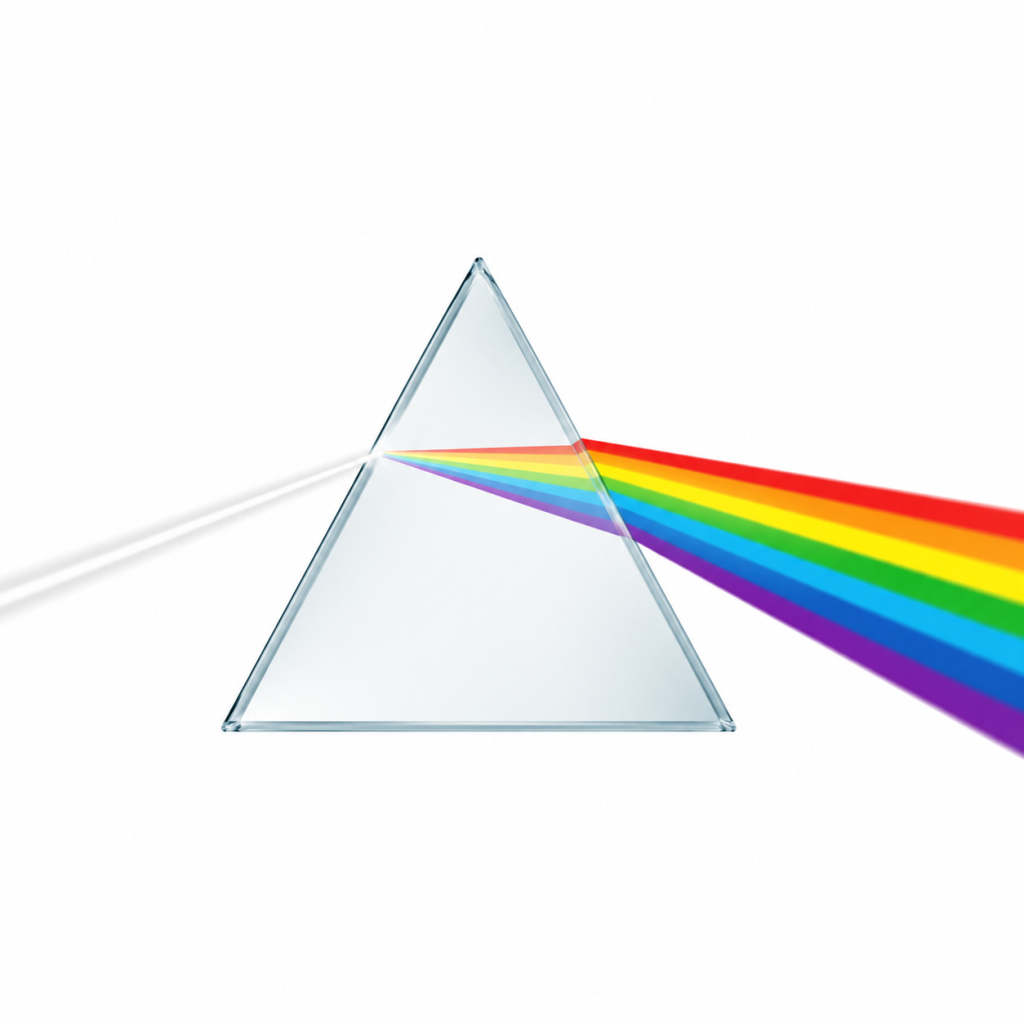
The most intuitive example of this is white light splitting into a colorful spectrum after passing through a プリズム, but this phenomenon is merely a surface manifestation. In engineering applications, dispersion typically introduces invisible, wavelength-dependent aberrations that are continuously amplified under multi-wavelength or broadband conditions, thereby degrading overall system performance.
What are the Principles of Optical Dispersion?
The fundamental cause of optical dispersion lies in the interaction between light waves and a material’s internal electronic structure as light propagates through it. When an electromagnetic wave enters a medium, its alternating electric field drives electrons in the material to undergo minuscule displacements, thereby inducing a polarization response. Because light waves of different frequencies (or wavelengths) interact with the bound states of electrons with varying intensities, the material’s response varies across wavelengths.
This variation yields a critical result: the refractive index is no longer a fixed constant, but rather a function of wavelength, expressed as:
n = n(λ)
Since the refractive index dictates the velocity of light within a medium, light of different wavelengths travels at slightly different speeds through the same material. After traversing identical optical paths, differences accumulate in their phase or propagation time, resulting in the dispersion effect.
It is important to emphasize that this relationship between the refractive index and wavelength is continuous but non-linear. Consequently, under narrowband light source conditions, these differences are usually minimal and difficult to observe. However, in broadband light sources or ultrashort pulse systems, the variations among different wavelengths accumulate and scale up over propagation distance, ultimately manifesting as pulse broadening or the spatial separation of distinct wavelength components.
Main Types of Optical Dispersion
1. Material Dispersion
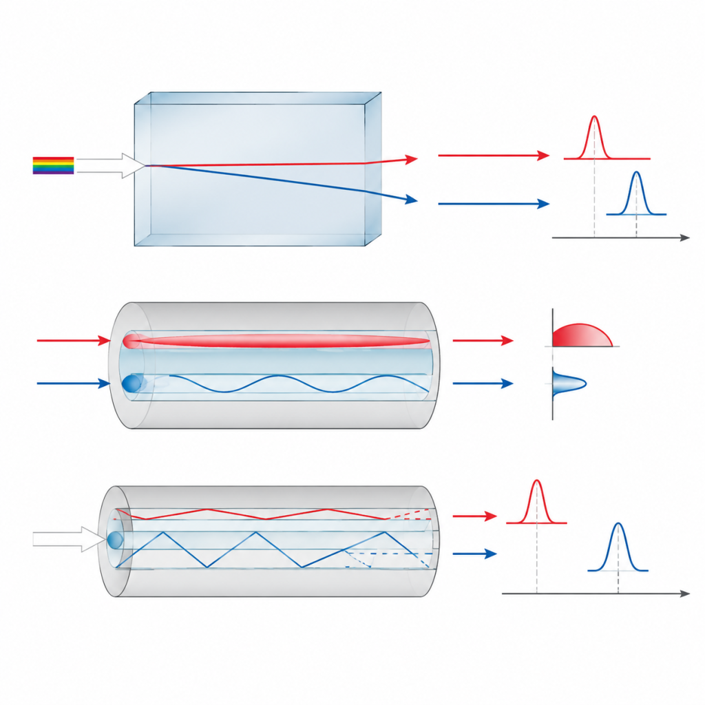
Material dispersion is the most fundamental type of dispersion, originating from the intrinsic response differences of the material itself to various wavelengths. Because internal electrons react differently to different frequencies of light, the propagation velocity of each wavelength changes within the material, causing the refractive index to vary with wavelength.
This phenomenon is present in virtually all transparent optical materials, such as glass, quartz, optical crystals, and polymers. In practical applications, it typically manifests as the inability of different colors of light to focus at the same position during broadband imaging, leading to minor focal shifts or color fringing along image edges.
2. Waveguide Dispersion
Waveguide dispersion is a dispersive effect caused by the geometric boundary conditions and structural constraints imposed on light as it propagates through a waveguide. Its essence stems from the transverse field distribution variations of light within a confined space, rather than changes in the bulk material’s refractive index over wavelength.
In a waveguide structure, even if the material’s intrinsic dispersion remains constant, light of different wavelengths will still exhibit variations in their effective refractive index due to differing mode field distributions and boundary conditions. This wavelength dependence of the effective refractive index constitutes the primary source of waveguide dispersion.
Key Distinction:
Waveguide dispersion must be clearly distinguished from modal dispersion. Waveguide dispersion describes how the propagation constant of a single mode within a structure varies with wavelength, whereas modal dispersion arises from path and group delay differences between multiple distinct propagation modes.
Waveguide Structure:
This can be understood as an architecture designed to constrain the propagation path of light. By utilizing refractive index differentials or physical boundaries, it confines light within a designated channel, preventing it from diffusing outward freely and forcing it to propagate in a specified direction.
For instance, in an optical fiber, light is confined within the central core region as it travels forward; in photonic chips, specialized microstructures carve out precise propagation pathways. Simply put, a waveguide structure transforms light from a freely propagating wave in open space into a highly controllable wave along a specific path.
3. Modal Dispersion
Modal dispersion occurs predominantly in multimode optical fibers. Its root cause is that a single beam of light injected into a fiber decomposes into multiple propagation modes. These distinct modes traverse different paths—some take a direct linear path, while others propagate via multiple total internal reflections. Consequently, even if they share the same starting point, their arrival times at the destination vary.
Note that this mechanism is entirely distinct from material dispersion. Material dispersion is driven by velocity variations caused by the refractive index changing with wavelength. In contrast, modal dispersion occurs at a single wavelength, arising purely from arrival time differences due to varying geometric paths, completely independent of the material’s intrinsic dispersive properties.
This time differential causes an originally compact optical pulse to gradually widen during propagation—a phenomenon known as pulse broadening—which degrades the time-resolution capabilities of the system. In high-speed optical communications, this broadening causes adjacent signals to overlap, increasing the bit error rate (BER). As a result, modal dispersion is typically one of the critical limiting factors for the transmission distance and bandwidth of multimode fibers.
Propagation Mechanisms and System Manifestations
From a system-level perspective, dispersion yields various consequences across imaging, laser, and communication systems. However, the root of these phenomena lies entirely in how light evolves during propagation. To fully understand these system-level behaviors, it is necessary to analyze the propagation process itself—specifically, how different frequency components evolve through a medium.
1. Group Velocity Dispersion (GVD)
Group Velocity Dispersion (GVD) describes the differences in group velocity among various frequency components. That is, light of different frequencies travels at different speeds along the propagation path, causing an optical pulse to broaden along the time domain. GVD is a core concept in ultrafast optics and femtosecond laser systems, used to quantify the temporal evolution of a pulse inside a medium.
In the frequency domain, GVD reflects the second-order derivative of the propagation constant with respect to the angular frequency. Therefore, it directly dictates the rate at which a pulse broadens per unit of propagation distance, making it an indispensable parameter for analyzing ultrashort pulse propagation.
2. Phase Dispersion
Phase Dispersion describes the relationship between the phase of a light wave and its frequency, meaning that different frequency components accumulate unequal phases during propagation. It is typically utilized in frequency-domain analysis and serves as a vital foundation for understanding wave propagation, interference, and Fourier optical systems.
While phase dispersion does not directly manifest as “temporal broadening” on its own, it is the underlying source of group velocity dispersion. The two are mathematically linked via the derivative relationship of the phase function with respect to frequency, meaning both must generally be considered simultaneously in theoretical optical analysis.
Manifestations of Optical Dispersion in Systems
1. Chromatic Aberration
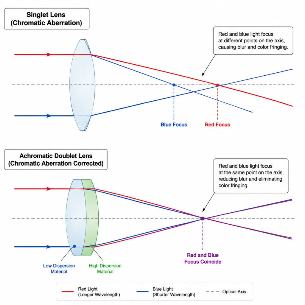
Chromatic aberration is one of the most typical wavelength-dependent errors in imaging systems, representing the direct manifestation of material dispersion within an optical layout. Because the refractive index of optical materials varies with wavelength, different colors of light bend at slightly different angles when passing through a lens. This creates spatial positional shifts in the image space, preventing different wavelengths from converging precisely onto the same focal plane.
Depending on how it manifests, chromatic aberration is generally categorized into two types:
- Axial (Longitudinal) Chromatic Aberration: Manifests as the focal points of different wavelengths splitting forward and backward along the optical axis.
- Lateral (Transverse) Chromatic Aberration: Manifests as varying magnifications for different wavelengths across the image plane, leading to color registration misalignments.
In final imaging outputs, chromatic aberration typically shows up as colored fringes around image edges, a drop in fine detail contrast, and a reduction in overall resolution. In multi-lens systems, this error accumulates across sequential stages, compounding with other geometric aberrations to further degrade final image quality.
2. Pulse Broadening
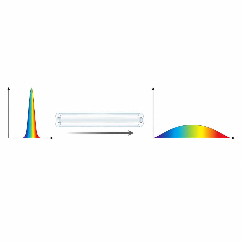
Pulse broadening occurs primarily in ultrafast laser systems and optical fiber transmission systems. Its essence lies in the fact that different wavelength components possess distinct group velocities during propagation, causing an optical pulse to stretch out progressively along the time axis. When a short pulse contains a broad spectrum of wavelengths, their mismatched velocities mean that as transmission distance increases, the originally compact temporal structure stretches, resulting in increased pulse duration and a corresponding drop in peak power.
In ultrafast laser applications, this broadening reduces instantaneous energy density, which impairs material processing precision and weakens nonlinear optical efficiencies. In optical communication systems, it degrades time-domain resolution, causing signal boundaries to blur and placing heavier demands on downstream signal processing.
3. Signal Distortion
Signal distortion occurs primarily in digital 光通信 systems and represents the cumulative impact of dispersion at the information-transmission layer. As optical signals travel along a fiber, different frequency components separate due to velocity disparities. This deforms and widens the originally crisp digital pulses, eventually causing adjacent signals to spill into one another.
This overlap triggers Intersymbol Interference (ISI), making it difficult for the receiver to accurately determine bit states. This increases the bit error rate (BER) and strictly limits both the transmission distance and the data rate of the system. In high-speed, long-haul communication links, this type of distortion must be systematically corrected using optical dispersion compensation hardware or advanced digital signal processing algorithms.
Control and Compensation Methods for Optical Dispersion
While optical dispersion cannot be eliminated from physical systems, it can be managed effectively through strategic material selection, structural engineering, and system-level compensation techniques. The core objective across all levels is to mitigate or cancel out the negative impacts of various dispersion types to maximize imaging or transmission performance.
1. Material Selection Optimization
Controlling dispersion at the material level relies on selecting optical media with low-dispersion characteristics—specifically, materials whose refractive indices change minimally across target wavelengths—thereby mitigating material dispersion at its source. The primary metric used to evaluate this is the Abbe number. The Abbe number quantifies the degree to which a material’s refractive index varies relative to wavelength; a higher Abbe number indicates that the material’s refractive index is less sensitive to wavelength changes, meaning its dispersion effects are weaker. Consequently, high-Abbe-number materials are highly advantageous for minimizing focal shifts and chromatic aberrations in broadband systems.
Common high-Abbe-number materials include:
- Fluoride glasses (e.g., CaF₂, MgF₂)
- Specialized Extra-low Dispersion (ED) glasses
- Optical-grade fused silica (quartz)
These materials share a common trait: their refractive index curves remain relatively flat across a wide spectral range, making them ideal for dispersion-sensitive imaging or multi-wavelength applications.
Engineering Note:
A high Abbe number does not equate to a high refractive index; they are separate parameters. High-refractive-index materials are prized for making optical layouts compact, whereas high-Abbe-number materials are used for dispersion control. In practical engineering, designers must balance refractive index and dispersion to meet overall system requirements.
2. Achromatic and Apochromatic Design
Achromatic design is a classic method of compensating for dispersion through structural optics. The core strategy is to combine optical materials with contrasting dispersion properties so that different wavelengths of light converge back to the same focal position after passing through the system, thereby neutralizing chromatic aberration over a designated operating band.
In a typical implementation, an achromatic design utilizes a doublet lens structure. This configuration pairs optical materials with positive and negative dispersion characteristics—such as crown glass and flint glass. By precisely matching the refractive indices and dispersion curves of the two elements, the focal points for two specific target wavelengths (usually red and blue light) are forced to coincide. This effectively corrects axial chromatic aberration, though some residual secondary spectrum aberration remains across the wider wavelength band.
デザインタイプ | Wavelength Adjustments | Structural Complexity | 一般的なアプリケーション |
Achromatic | Corrects two wavelengths (typically Red & Blue) | Moderate (typically a doublet layout) | General imaging, consumer optics, standard sensors |
Apochromatic | Corrects three or more wavelengths simultaneously | High (triplet layouts, specialized ED glasses) | High-res microscopy, precision metrology, multispectral systems |
Apochromatic design expands upon achromatic principles. Rather than correcting for just two wavelengths, it targets three or more wavelengths simultaneously, maintaining superior imaging consistency across a much broader spectrum. To achieve this, apochromatic systems introduce a wider array of optical materials paired with complex structural optimizations to satisfy imaging conditions at multiple reference points concurrently.
While it dramatically reduces residual chromatic aberration, its design complexity, material costs, and manufacturing tolerances are significantly higher than standard achromatic options.
3. Diffractive Optical Compensation
Diffractive Optical Elements (DOEs) manage light wave phase distributions through micro- or nano-scale surface structures. Unlike traditional refractive lenses that rely on bulk refractive index changes, DOEs introduce precisely engineered micro-patterns on their surfaces to generate predetermined phase delays, enabling precise control over beam propagation directions and wavefront shapes.
Compared to refractive elements, DOEs possess a uniquely valuable trait: their dispersion behavior is highly customizable through geometric design. In a refractive system, dispersion is rigidly dictated by the intrinsic properties of the material. In a diffractive structure, however, the way different wavelengths undergo phase modulation at the microstructural boundaries can be engineered to exhibit a negative dispersion coefficient. This negative dispersion can be deliberately designed to oppose and cancel out the positive dispersion of refractive elements.
In engineering applications, DOEs offer lightweight profiles, thin form factors, and high integration potential, making them exceptionally well-suited for space-constrained or multi-element integrated systems. Furthermore, they are frequently paired with refractive optics to create refractive-diffractive hybrid systems. These hybrids achieve wideband dispersion correction while keeping the system compact, and are widely deployed in high-performance imaging, laser beam shaping, and optical fiber communications coupling.
4. Dispersion Compensation Techniques in Optical Communications
In optical communication systems, dispersion accumulates continuously along the entire transmission link. As a result, compensation strategies rarely rely on a single device; instead, they employ a layered architecture tailored to the link structure to achieve global optimization. Based on implementation location and methodology, these techniques fall into three categories:
Fiber-Level Compensation: Dispersion Compensating Fiber (DCF)
Dispersion Compensating Fiber (DCF) introduces a segment of fiber engineered with negative dispersion characteristics to counteract the positive dispersion accumulated along standard transmission fibers. The core approach involves inserting a specific length of fiber with an opposing dispersion slope into the transmission link, causing the temporal pulse broadening generated during propagation to be “reverse-compressed.” This approach acts directly on the physical path of the optical signal, providing a direct hardware-level correction suitable for long-haul transmission lines. However, its drawbacks include added insertion loss and increased system complexity, which must be carefully balanced during link budgeting.
Optical Device Compensation: Fiber Bragg Gratings (FBG)
Fiber Bragg Gratings (FBGs) leverage periodic refractive index modulations inside the fiber core to create selective reflection and delay profiles for different wavelengths. This allows for precise adjustments to the arrival times of various frequency components. Unlike DCF, an FBG achieves correction through wavelength-selective delay management. FBGs feature a compact footprint, low insertion loss, and easy integration, making them ideal for short-to-medium link distances or localized, high-precision tuning scenarios.
Digital Signal Processing (DSP) Compensation
Digital Signal Processing (DSP) is an algorithmic approach executed at the receiver end to mathematically reconstruct signals that have suffered dispersive distortion. The fundamental principle involves using the known dispersion profile of the optical channel to apply inverse convolutions or filtering algorithms to the digitized incoming data, thereby restoring the original temporal structure of the pulse. This method bypasses optical hardware additions, resolving dispersion entirely in the electrical domain. Its high adaptability and flexibility make it a cornerstone of modern high-speed coherent optical communication networks.
System-Level Collaborative Compensation
In modern optical engineering, these three methodologies are rarely deployed in isolation. Instead, they are combined based on link distance, data rates, and cost considerations. For example, in a long-haul backbone network, DCF may be deployed for coarse bulk compensation, FBGs used for localized optimization at nodes, and DSP utilized at the terminal receiver for final error corrections, establishing comprehensive, link-wide dispersion management.
結論
Optical dispersion is an inescapable, fundamental physical attribute arising from the interaction between light and matter, and it is universally present across all optical systems. Beyond generating wavelength-dependent focal shifts or temporal pulse broadening, it fundamentally dictates imaging precision, signal integrity, and energy transfer efficiency.
As high-resolution imaging, multi-wavelength architectures, and high-speed optical communications continue to advance, securing stable, controllable, and uniform optical components remains a vital prerequisite for building high-performance systems. Hobbite delivers tailored solutions across material selection and structural optimization for 光学素子 and customized assemblies. These offerings support diverse applications across multi-band imaging, telecommunications, and precision optics, providing foundational engineering support for rigorous dispersion control in complex optical systems.