Optical fiber is a transmission medium that utilizes light signals for information transfer. Its core principle relies on total internal reflection, allowing light to propagate through a fiber core with exceptionally low attenuation. Compared to traditional electrical signal transmission, optical fiber offers significantly higher bandwidth, lower attenuation, and immune performance against electromagnetic interference (EMI). Consequently, it has become a foundational pillar of modern telecommunication networks, data centers, and various complex optical systems.
From a functional standpoint, the primary purpose of an optical fiber extends beyond simple transmission; it is designed to achieve long-distance, high-speed, and stable data routing while preserving signal integrity. Throughout this process, the propagation characteristics of light, optical path routing, and coupling efficiency with external optical components and optic lenses directly govern overall system performance.
Based on the distinct propagation modes of light within the waveguide, optical fibers are split into two primary categories: single mode fiber and multimode fiber. The fundamental difference between single mode fiber vs multimode fiber lies in their core dimensions and the number of concurrent propagation modes they support. Single mode fiber restricts transmission to a solitary mode, whereas multimode fiber permits multiple modes to coexist simultaneously. This structural divergence leads to completely different modal dispersion profiles and transmission performance, ultimately defining their bandwidth boundaries and maximum reach.
Single Mode Fiber (SMF)
1. Definition and Structure
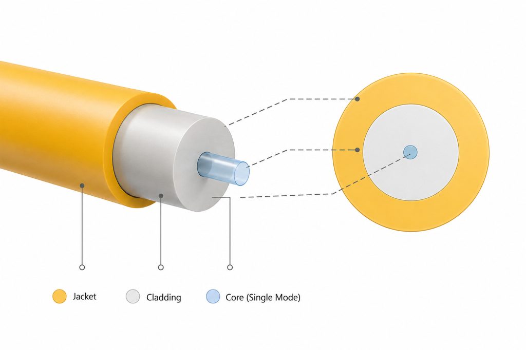
A single mode fiber (SMF) is an optical waveguide structure that strictly controls core dimensions and the refractive index profile to restrict light propagation to a solitary mode. Its core diameter typically ranges from 8 to 10 microns, which is substantially smaller than that of a multimode fiber. This minute scaling is not merely a physical reduction but a calculated geometric constraint based on waveguide theory to isolate a specific propagation mode.
Structurally, single mode fiber consists of a central core surrounded by a cladding layer, where the refractive index of the core is slightly higher than that of the cladding to trap light via total internal reflection. When the core diameter is minimized below a specific threshold, only the fundamental mode (LP01 mode) can stably propagate, while all higher-order modes fail to satisfy boundary conditions and are suppressed or rapidly attenuated. This single-mode condition is the physical origin of the fiber’s nomenclature.
This geometry ensures that the propagation path of light is highly concentrated along the axial centerline, virtually eliminating path branching or multi-angle reflections. This layout establishes the foundation for low dispersion and high-fidelity signal transmission. However, the small core aperture demands rigorous light coupling conditions, typically requiring 고정밀 광학 부품 and optic lenses to execute stable alignment.
2. Working Principle and Advantages
The primary advantage of single mode fiber stems from the absolute singularity of its propagation mechanism. In a multimode system, light rays travel along varied trajectories, with each path corresponding to a different propagation time, which induces pulse broadening (known as modal dispersion). In a single mode fiber, because only one propagation mode exists, all light signals arrive at the receiver terminal almost simultaneously in the time domain, neutralizing modal dispersion at the physical level.
This property enables single mode fiber to preserve wavefront and pulse integrity over long haul distances, preventing inter-symbol interference (ISI) and supporting hyper-high data rates over extreme distances. Furthermore, because the optical energy is confined within a microscopic cross-sectional area, scattering and diffusion losses are minimized. This results in an exceptionally low attenuation profile, typically hitting around 0.2 dB/km in the 1550 nm spectral window.
In terms of bandwidth capacity, single mode fiber is theoretically unconstrained by mode volume; its ultimate throughput is governed almost entirely by the performance of the transceiver hardware and system architecture. This allows it to scale from 10G and 100G up to 400G and beyond, making it the standard choice for metropolitan area networks (MANs), backbone networks, and data center interconnects (DCIs).
Additionally, in high-precision engineering frameworks—such as laser delivery, optical sensing arrays, and LiDAR configurations—single mode fiber delivers superior, stable beam quality and pairs seamlessly with laser optical systems to guarantee focal spot uniformity and metrology accuracy.
3. Limitations
Despite its clear performance advantages, the physical configuration of single mode fiber introduces steeper engineering challenges. First, the sub-10-micron core diameter dictates that the incoming light signal must be coupled into the core with absolute precision; even a microscopic sub-micron misalignment can cause coupling efficiency to plummet or trigger severe insertion loss. Therefore, system integration mandates the use of high-precision alignment fixtures and premium optic lenses to achieve long-term connectivity.
Second, single mode fiber requires high-performance light sources with narrow spectral linewidths and tight directional profiles, such as semiconductor laser diodes, ruling out the use of low-cost LEDs with wide divergence angles. This increases the baseline hardware cost of the transceivers and introduces stricter demands for driving circuitry and thermal management.
Finally, across short-reach architectures, the cost-benefit ratio of single mode fiber becomes less favorable. Within dense enterprise local networks or localized data center switch fabrics requiring thousands of port connections, the cumulative cost of high-precision connectors and laser-based transceivers often proves less economical than implementing a multimode alternative. Thus, while single mode fiber delivers superior raw performance, engineering deployment still requires a balanced trade-off between transmission distance, financial budget, and overall system complexity.
Multimode Fiber (MMF)
1. Definition and Structure
A multimode fiber (MMF) is an optical waveguide engineered with a much larger core dimension, typically featuring a core diameter of 50 microns or 62.5 microns. Unlike single mode architectures that restrict wave propagation, the physical design of a multimode fiber allows hundreds of distinct spatial modes to propagate concurrently, meaning light can travel through the core along multiple independent optical paths.
Structurally, multimode fiber is also comprised of a core and a cladding layer, but its expanded core aperture provides a massive spatial tolerance for incoming light, eliminating the need for hyper-sub-micron alignment during connection. This characteristic makes multimode fiber significantly easier to install, terminate, and maintain in field environments. Regarding the refractive index profile, multimode fibers are classified into step-index and graded-index structures. Modern graded-index profiles feature a parabolic index distribution that peaks at the core center and tapers toward the cladding interface; this configuration accelerates higher-order modes traveling along the outer edges to equalize propagation time delays, partially mitigating modal dispersion.
Because it supports multi-mode propagation, light inside a multimode fiber is not restricted to axial propagation; instead, it undergoes repeated total internal reflections at varying angles of incidence along the core-cladding boundary, generating complex geometric ray paths. While this structural characteristic underpins its ease of use, it simultaneously acts as the primary bottleneck limiting its long-range performance.

2. Working Principle and Advantages
The operational mechanics of multimode fiber are built entirely upon multi-path propagation. When an optical signal is launched into the core, light rays entering at different angles trace unique trajectories: some travel almost in a straight line along the center axis, while others bounce repeatedly off the walls at steep angles. Because these paths vary in total physical length, the corresponding arrival times of the light pulses shift, culminating in modal dispersion.
Although modal dispersion caps its long-distance capabilities, its impact remains highly manageable within short-range links, allowing multimode fiber to deliver ample bandwidth to support high-speed local data transfers. This is especially true when deploying modern graded-index designs, where path-induced time delays are systematically minimized to unlock much higher modal bandwidths.
The overriding advantage of a multimode fiber framework is centered on total system cost and deployment convenience. Its large core diameter permits the use of cost-effective, wide-divergence light sources like vertical-cavity surface-emitting lasers (VCSELs) or standard LEDs. Furthermore, because its alignment tolerances are forgiving, it does not require complex optical components or ultra-high-precision optic lenses to establish a stable, low-loss link. This makes multimode fiber incredibly valuable inside localized data centers, local area networks (LANs), and horizontal building backbones.
Additionally, in high-density patch environments, the relaxed alignment margins of multimode connectors mitigate the risk of dust contamination and insertion loss anomalies, driving down deployment difficulty and operational maintenance overhead.
3. Limitations
The core constraint of multimode fiber is tied to its multi-path propagation nature. As the physical link distance increases, individual light pulses spread out along the time domain, inducing severe inter-symbol interference. This phenomenon sets a strict ceiling on both system bandwidth and maximum allowable distance. Even within advanced graded-index profiles, this dispersion penalty can only be suppressed, never entirely eradicated.
Consequently, multimode fiber is generally restricted to transmission distances spanning from a few hundred meters up to two kilometers. Past these limits, the modal bandwidth drops off sharply, rendering it unusable for long-haul telecommunications or ultra-fast wide area networks.
Moreover, as network speeds scale up to 100G, 400G, and beyond, the link power budget for multimode architectures tightens drastically. Factors such as connector quality, fiber macrobending losses, and modal launch distributions start to severely impact link stability. As a result, the ongoing evolution toward higher speeds has led to single mode fiber progressively encroaching on territory traditionally dominated by multimode fiber.
Comparison Matrix: Single Mode Fiber vs Multimode Fiber
Evaluation Metric | Single Mode Fiber (SMF) | Multimode Fiber (MMF) |
Core Diameter | Approximately 8–10 µm | 50 µm or 62.5 µm |
Propagation Modes | Solitary Mode (Single Path) | Multiple Modes (Multi-path Concurrently) |
Propagation Mechanism | Travels almost linearly along the axis with near-zero path deviation | Bounces repeatedly within the core via complex geometric reflections |
Modal Dispersion | Inherently Near-Zero | High (Partially mitigated via Graded-Index) |
Bandwidth Capacity | Exceptionally High (Governed by transceivers) | Limited (Capped by modal dispersion) |
Transmission Reach | Tens of kilometers up to hundreds of kilometers | Typically limited to hundreds of meters up to 2 km |
Signal Attenuation | Very Low (~0.2 dB/km at 1550 nm) | Relatively High (~3.0 dB/km at 850 nm) |
Light Source Compatibility | Narrow-line Lasers (Laser Optical Modules) | Low-cost LEDs or VCSELs |
Coupling Complexity | High; requires tight-tolerance optic lenses and optical elements | Low; highly forgiving alignment margins |
Installation & Alignment | Demands extreme sub-micron precision | Highly manageable in field environments |
System Cost Structure | Higher initial transceiver costs; optimized for long-term scalability | Lower initial hardware and connector costs for short runs |
Primary Use Cases | Long-haul telecom, MAN backbones, DCI networks | Local Area Networks (LANs), intra-datacenter fabrics |
Engineering Selection Guide
In practical network engineering, selecting between single mode fiber vs multimode fiber is not a simple choice of picking a product category; it requires a balanced calculation across three key vectors: link distance, bandwidth targets, and total deployment budget.
When your architecture demands extended reach or high-capacity scalability, single mode fiber is the definitive choice. In metropolitan area networks, carrier backbones, or data center interconnects, link distances routinely cross multiple kilometers. These paths require absolute signal fidelity and minimal waveform distortion. The modal dispersion found in multimode fiber would collapse the bandwidth within a few hundred meters, whereas single mode fiber maintains crisp pulse boundaries over long distances due to its single-path physics. Additionally, in specialized optical designs like laser delivery or sensor arrays, single mode fiber provides a cleaner, more stable beam profile that pairs optimally with specialized laser optical systems.
Conversely, when your link distances are short and your project is highly sensitive to upfront transceiver costs and installation speeds, multimode fiber offers a more efficient path forward. Inside localized data center server rows, horizontal office runs, and short equipment cross-connects, link runs typically stay under a few hundred meters. Within this footprint, the degradation from modal dispersion is minimal. The wider core of multimode fiber dramatically lowers coupling difficulty, enabling the use of low-cost VCSEL transceivers and reducing the system’s reliance on high-tolerance optical components and specialized optic lenses. This keeps installation straightforward and minimizes upfront capital expenditure.
Why Must Patch Cords and Pigtails Match the Fiber Type?
In an optical link, patch cords and pigtails are frequently treated as simple, passive connection hardware. However, from a physical optics standpoint, they act as active extensions of the core waveguide channel. Their core dimensions must align perfectly with the backbone cable plant. This strict requirement is dictated by the wave propagation mechanics of light.
If a multimode patch cord is mistakenly installed into a single mode link, the light exiting the narrow single-mode core will instantly spread into the much wider multimode core. This shift forces the light to propagate across multiple paths, inducing modal dispersion, disrupting the stable single-mode transmission profile, and introducing massive attenuation and signal distortion.
Conversely, splicing a single mode pigtail into a multimode system creates a severe geometric bottleneck. The light traveling along the wide multimode core will strike a physical boundary when hitting the tiny single-mode core, resulting in massive aperture mismatch, high insertion loss, and a drop in overall system performance.
Furthermore, single mode and multimode fibers are engineered with completely different core dimensions, numerical apertures (NA), and spot size characteristics. Their internal mating sleeves, ferrule geometries, and alignment optics are optimized specifically for their respective dimensions. This is why every single component in an optical train—from the backbone cable to the patch cords, pigtails, and transceiver modules—must remain perfectly consistent in fiber type. Maintaining this consistency across the physical layer is the only way to avoid systemic link failures.
결론
The core difference when comparing single mode fiber vs multimode fiber points directly back to their physical core dimensions and the resulting mode volume. Single mode fiber restricts light to a single propagation path, eliminating modal dispersion to deliver low attenuation and high bandwidth across long distances. In contrast, multimode fiber allows multi-path propagation, which provides a highly forgiving coupling profile and keeps transceiver costs low, even though its native modal dispersion limits its long-range performance.
Because of these trade-offs, neither fiber type is universally superior; instead, they serve separate, distinct roles across network engineering. When a project demands extended reach, pristine signal integrity, or precision beam control, single mode fiber is the optimal choice. When the layout is compact, short-range, and requires fast deployment within a tight budget, multimode fiber provides a highly pragmatic, cost-efficient solution.
In the final system design, choosing your optical fiber should never be done in isolation. It must be carefully evaluated alongside your light source selection, transceiver modules, internal optical components, and optic lenses to guarantee absolute consistency across the physical layer. Understanding how these two propagation mechanisms differ is the foundational requirement for building stable, optimized, and high-performance optical networks.