Optical fabrication refers to a complete set of processing procedures for manufacturing optical components such as lenses and prisms, rather than a single process. Every step in the entire process is closely linked to the final finished product: the processing state of the early stages will affect the processing quality of the subsequent stages, and if a problem occurs in any step, the final optical component may fail to meet the original design specifications. Therefore, this set of processes must be fully followed and cannot be arbitrarily omitted or skipped.
These steps are developed around the machinability limits of materials, the stability of the processing process, and the gradual convergence of precision. Improper control may ultimately manifest as unstable optical performance.
Raw Material and Blank Preparation
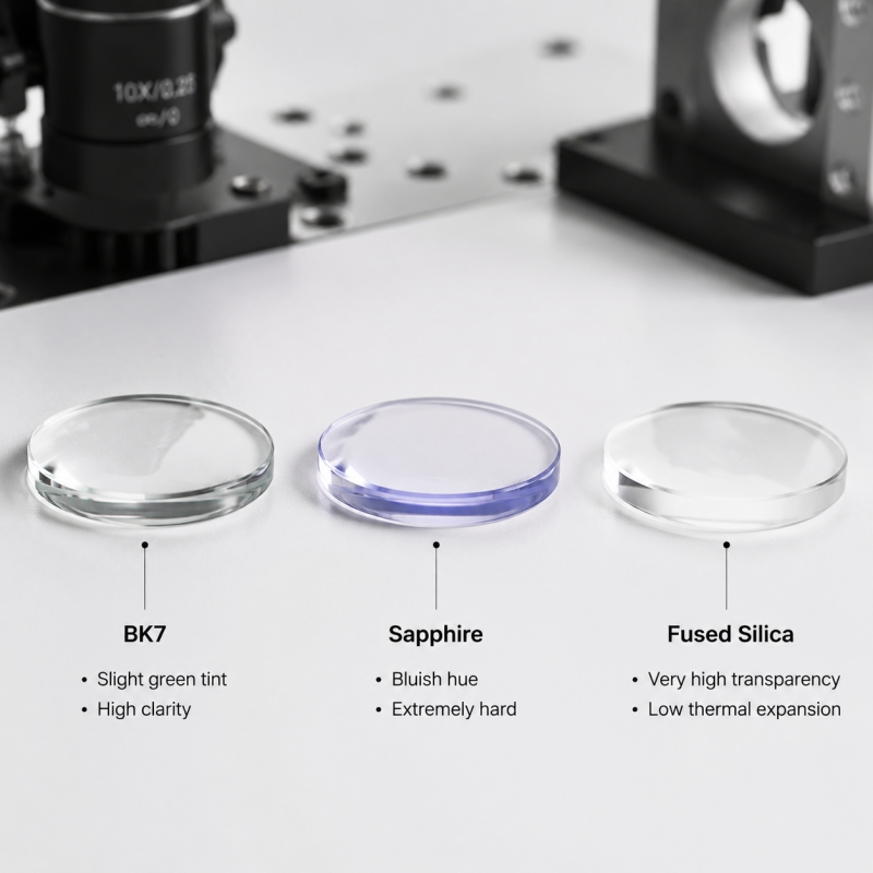
Optical fabrication begins with the initial state of optical materials before processing. Whether they are common optical glass, hard crystalline materials, or polymer optical materials, the internal purity directly affects the controllability of the subsequent processing process.
Therefore, the focus of manufacturing at this stage is not on whether the geometric dimensions meet the standards, but on whether the materials have undergone sufficient annealing, whether the internal stress is uniformly released, and whether there are macroscopic defects such as bubbles, striae, or compositional inhomogeneity. These issues are often not immediately apparent in early processing, but may be concentratedly exposed after high-precision polishing or coating, directly affecting the final imaging quality.
Thus, in optical fabrication, the selection and preprocessing of blanks directly determine whether the subsequent processes can proceed stably.

Cutting and Thickness Calibration
After blank preparation, optical components enter the cutting and thickness calibration stage. The goal of this step is to cut the material into a shape convenient for processing and adjust the thickness to meet the basic design requirements approximately.
- Cutting: It refers to using special cutters or saw blades to cut large glass blocks or crystal blanks into the approximate contours required for optical components, such as circular wafers or rectangular blocks. Cutting does not require extremely high precision; it is mainly to facilitate subsequent processing and reduce material waste.
- Thickness Calibration: It refers to grinding the surface of the cut optical component to a thickness close to the target through lapping or grinding, ensuring the uniform thickness of the front and rear surfaces. This step guarantees the dimensional consistency of optical components and provides a unified starting point for subsequent rough grinding, fine grinding, and polishing.
Special attention needs to be paid to controlling the formation of edge microcracks during cutting. Excessive cutting stress can easily introduce deep cracks or even chipping at the material edges. Such defects are often difficult to completely remove in subsequent grinding and may continue to propagate inside the material. Although the thickness calibration process seems simple, it directly affects the uniformity of machining allowance distribution. If the thickness deviation is too large, uneven pressure distribution is likely to occur in subsequent grinding, thereby introducing new surface shape problems. This step ensures more stable subsequent processing and reduces error accumulation.
Generating
Generating is one of the most misunderstood processes in optical fabrication. Its main goal is to roughly grind the material into the contour required by the design in a stable and controllable manner—such as the curved surface of a lens or the inclined surface of a prism—without pursuing the final high precision.
Tools and Operation Methods for Generating
- Diamond Wheel / Grinding Wheel: Mainly used to remove surplus material from optical blanks and quickly grind the material into a shape close to the design contour. The high-hardness diamond wheel can perform high-speed cutting on glass or crystal without damaging the tool itself.
- Generating Machine: Realizes uniform cutting or grinding by fixing the optical component and controlling rotation and feed. It can ensure precise control of pressure and moving speed, guaranteeing stable shaping without local over-cutting or inhomogeneity.
- Cooling and Lubrication Device: Provides cooling fluid during high-speed cutting with a diamond wheel to prevent material overheating or crack generation, ensure the material structure is not damaged, and remove chips produced by cutting.
- Clamps or Support Tables: Fix the optical component to avoid movement or shaking during cutting or grinding. Due to the brittle and hard nature of optical materials, excessive clamping may cause cracking, requiring special supports or flexible clamps.
At this stage, manufacturing focuses more on the uniformity of material removal and the stability of the processing process, rather than whether the curvature has entered the final tolerance range. Premature pursuit of high precision in the generating stage may easily introduce local stress concentration, compressing the correction space for subsequent grinding and polishing. This risk is particularly prominent for materials with high hardness or obvious anisotropy.

Rough Grinding
Rough grinding is an important stage in optical fabrication, whose main goal is to remove surplus material from the surface of the optical component after generating and further bringing the shape close to the design requirements. At this stage, surface precision is not required to be perfect, but the shape must be similar or stable to prepare for subsequent fine grinding and polishing.
The main tools used for rough grinding are relatively coarse grinding wheels or diamond grinding heads, which grind optical components through mechanical rotation or reciprocating motion. These tools can efficiently remove surplus material without damaging the material structure when controlled properly. Cooling fluid is usually employed in the process to prevent material overheating or crack formation.
Special attention must be paid to balancing the abrasive particle size, applied pressure, and material removal rate during operation. Excessively fast speed or high pressure will form microcracks beneath the surface, a type of damage known as Subsurface Damage—referring to microcracks and structural damage generated beneath the material surface during grinding—which is difficult to eliminate in subsequent processing.
The criteria for successful rough grinding are: the material surface roughly conforms to the design contour, the thickness is uniform, and there are no obvious cracks or damage. The surface may still be rough, but the stable shape allows entry into the fine grinding stage. This process may involve correcting uneven material removal, local over-cutting, or excessive subsurface damage. If these problems occur, they will be difficult to correct in subsequent fine grinding and polishing, possibly leading to increased scattering or unstable surface shapes. Therefore, the core of the rough grinding stage is uniform material removal and controllable damage, rather than pursuing a smooth surface or perfect curvature.
Comparison Table: Generating vs Rough Grinding
| Process | Main Objectives | Tools Used | Processing Method | Success Criteria | Precautions/Risks |
|---|---|---|---|---|---|
| Generating | Rapidly remove surplus blank material and establish the approximate shape (e.g., curved lens contour or inclined prism surface) | Diamond wheel, grinding wheel, and generating machine | High-speed rotational or reciprocating cutting for rapid material removal | Correct approximate shape and roughly compliant thickness | Rough surface is acceptable; avoid premature high precision to prevent local stress concentration |
| Rough Grinding | Further bring the shape close to the design curvature and thickness while controlling material damage (Subsurface Damage) | Coarser grinding wheel/diamond grinding head, lapping machine | Control feed speed and grinding pressure for uniform material removal | Uniform thickness, shape close to design, no deep surface cracks | Excessive pressure or speed may cause serious subsurface damage, affecting subsequent fine grinding and polishing |
Fine Grinding
Fine grinding is a key link connecting rough grinding and final polishing. Its main purpose is to further refine the shape of the optical component, control residual internal material damage, and lay the foundation for high-precision polishing. Rough grinding removes most surplus material, while fine grinding makes the optical component surface “more accurate and flat”, ensuring effective correction in subsequent polishing.
The tools used for fine grinding are usually fine-grained diamond grinding heads or fine grinding wheels, with finer abrasives and slower material removal rates than rough grinding. Optical components are fixed on fine grinding machines or lapping machines and uniformly ground through rotation and reciprocating motion, with cooling fluid employed in the process to prevent material overheating or crack formation. Compared with rough grinding, fine grinding operations are more meticulous, focusing on controlling the uniformity of material removal and damage convergence.
Several key indicators mainly judge the success of fine grinding:
- Surface Figure Error: The deviation between the actual surface of the optical component and the designed ideal surface. Simply put, it is how closely the optical component’s surface shape matches the design target.
- Subsurface Damage: Microcracks or structural damage formed beneath the material surface during grinding. These invisible microcracks affect subsequent polishing results and optical performance. The fine grinding stage requires residual damage to be shallow and uniform for effective correction by polishing.
- Surface Roughness: The degree of micro-undulations on the material surface. Although fine grinding smooths the surface, roughness is only one reference indicator; surface figure error and subsurface damage are the key factors determining the final optical quality.
- Mid- to Low-Spatial Frequency Error: Large-scale undulations or ripples on the optical component surface, which are usually difficult to completely eliminate through simple polishing. Poor control in fine grinding may result in unstable shapes even with a smooth surface, leading to reduced imaging quality.
In the fine grinding process, uniform material removal, stable pressure control, and reasonable abrasive particle size are the keys to meeting these indicator requirements. Improper operation may lead to unconverged subsurface damage or increased mid- to low-spatial frequency error, affecting subsequent polishing results. Compared with rough grinding, fine grinding places more emphasis on precision and damage control, rather than just rapid material removal.
Comparison Table: Rough Grinding vs Fine Grinding
| Process | Main Objectives | Tools Used | Processing Method | Success Criteria | Precautions/Risks |
|---|---|---|---|---|---|
| Rough Grinding | Remove surplus material after generating, and bring the shape close to the design requirements | Coarser grinding wheel/diamond grinding head, lapping machine | Control feed speed and grinding pressure for uniform material removal | Uniform thickness, shape close to design, no deep surface cracks | Excessive pressure or speed causes serious subsurface damage, affecting subsequent fine grinding and polishing |
| Fine Grinding | Further refine the shape, reduce surface figure error and subsurface damage, and prepare for polishing | Fine-grained diamond grinding head/fine grinding wheel, fine grinding machine | Slow and uniform grinding, control pressure, and feed to gradually converge the damage layer | Surface figure error within controllable range, shallow and uniform residual subsurface damage, improved surface roughness | Excessively fast or uneven grinding introduces mid- to low-spatial frequency error, leading to unstable shapes after polishing |

Polishing
Polishing is the only process in optical fabrication that directly affects optical performance. It not only polishes the surface of optical components to a smooth finish but also directly determines the final Surface Figure Accuracy (the deviation between the actual surface of the optical component and the designed surface), Light Scattering Level (the degree of irregular light scattering on the surface), and Optical Consistency (the performance consistency of components in the same batch or optical system).
The main tools used in the polishing process include the Polishing Tool/Pad and polishing slurry. Polishing tools can be made of flexible or rigid materials and remove material from the optical surface through rotational, reciprocating, or combined motion. Polishing slurry usually contains tiny abrasive particles, which are used to finely remove minor surface protrusions and protect the material from excessive damage. The entire process requires precise control of the pressure, position, and time of contact between the tool and the optical component.
One of the core parameters of polishing is the Removal Function—a process parameter used to describe the distribution characteristics of material removal per unit time during polishing. The stability of the removal function determines whether material removal is uniform and whether it is carried out according to the design curvature, thus directly affecting surface figure accuracy. Insufficient polishing will leave Medium- to High-Spatial Frequency Error (minor micro-undulations of medium to small scale on the optical surface), leading to increased scattering; while over-polishing may damage the established curvature relationship and introduce new deformation.
The key criteria for successful polishing are that the surface figure error is within the design requirements, the scattering level is low and uniform, and the optical performance is consistent. Unlike generating, rough grinding, and fine grinding, a smooth surface in the polishing stage is merely a superficial phenomenon—what matters more is that the shape is precise and the performance stable. Therefore, polishing is a sophisticated process highly dependent on process control and operational experience.

Centration and Edge Processing
After the surface of the optical component meets the design requirements, the manufacturing process enters the Centration and Edge Processing stage. The core goal of this stage is to ensure that the optical performance of the optical component is completely consistent with the design expectations in actual working conditions. Even if the precision of a single surface is high, the overall performance of the system may be significantly reduced if the component installation or optical axis alignment is incorrect.
Two key indicators need to be focused on in the centration stage:
- Decenter: The offset between the optical axis (the ideal center line of light propagation) and the mechanical axis (the reference axis for component installation) of the optical component. Decentration will lead to increased system aberration, i.e., blurred imaging or light deviation.
- Wedge Angle: The included angle formed by the non-parallelism of the two surfaces of the optical component. An excessively large wedge angle will also introduce aberration and increase the difficulty of assembly and adjustment.

In terms of operation, centration is usually completed through precision clamps and measuring instruments. The optical component is fixed on a finely adjustable bracket, and the decenter and wedge angle are measured through optical interferometers, aligners, or laser collimation systems. The position is finely adjusted until the design requirements are met. Edge processing involves fine grinding or polishing the component edges to make them flat and chip-free, while ensuring the component dimensions and installation fit precision.
The ultimate goal is to achieve the design requirement of coincidence between the optical axis and mechanical axis of the optical component (the degree of coincidence between the light propagation axis and the component installation reference axis in the optical system), with the decenter and wedge angle within the allowable tolerance range, and the edge dimensions and surface quality meeting the system installation requirements.
Inspection and Process Feedback
A Process Monitoring and Feedback mechanism is required in the optical manufacturing process. Without real-time inspection, optical fabrication can only rely on final product acceptance to judge quality. This method is prone to problems: optical components may meet surface requirements, but hidden shape errors or installation deviations cannot be detected promptly, leading to the repetition of the same errors in the next batch.
Therefore, inspection should not only exist at the end of the process but also be repeatedly involved in key processes. Through real-time or phased inspection, deviations can be detected in a timely manner, and process parameters can be adjusted, thus ensuring the stability and repeatability of each processing step.
Common inspection methods include:
- Surface Figure Measurement: Used to measure the deviation between the actual surface of the optical component and the designed ideal surface, helping to judge whether the optical shape meets the design requirements.
- Surface Roughness Measurement: An indicator reflecting the degree of micro-undulations on the optical surface. Excessively high surface roughness will increase scattering and affect imaging quality.
- Centration Measurement: Measures the offset between the optical axis and mechanical axis of the optical component, as well as the Wedge Angle (the included angle formed by the non-parallelism of the two surfaces of the optical component), ensuring the precise positioning of the optical component in the system.
Data obtained through these inspection methods can be continuously fed back into the processing process to guide professional technicians or automatic control systems to adjust parameters, avoiding the repetition of similar errors in subsequent batches.
Pre-Coating and Post-Coating Processing
At the end of optical fabrication, coating is often regarded as an independent process, but in fact, it is highly sensitive to the quality of previous processing. Surface cleanliness, residual stress, and micro-defects will be further amplified after coating.
If the stability of previous processing is insufficient, coating will not only fail to improve optical performance but may also introduce new uncertainties. Therefore, pre-coating and final post-coating processing are also indispensable parts of the optical fabrication process.
Conclusion
From blank preparation to final post-processing, every step of optical fabrication undertakes a clear and irreplaceable function. High-precision optical performance does not come from a single “key process”, but is gradually achieved through the gradual compression and control of errors in the entire process.
Understanding the optical fabrication process is essentially understanding how optical manufacturing achieves stable and repeatable engineering results under the boundary conditions of materials and precision.
FAQ
What is Optical Fabrication?
Optical fabrication refers to the complete manufacturing process used to produce optical components with controlled geometry, surface quality, and optical performance.
What are the main steps in Optical Fabrication?
The process typically includes material preparation, cutting, generating, rough grinding, fine grinding, polishing, centering, inspection, and post-processing.
Which step most affects optical performance?
Polishing has the most direct impact on optical performance, but its effectiveness depends heavily on the quality of all prior steps.
Why can’t the Optical Fabrication steps be simplified?
Because errors introduced at early stages are often amplified later and cannot be fully corrected, making each step essential to overall precision.