In many optical systems, engineers tend to focus on parameters like power, wavelength, or modulation methods. But collimation is just as important. Even a slight misalignment between the fiber and the collimator can lead to reduced energy coupling, abnormal beam divergence, or even a rapid degradation in beam quality (M²) that was otherwise close to ideal.
First, it helps to establish a basic understanding. M² (beam quality) is not just an abstract number—it directly reflects how closely a beam resembles an ideal Gaussian distribution. When M² is close to 1, the beam is easiest to control and propagates most stably. As M² increases, the beam becomes “looser,” and even if the power is sufficient, system performance will noticeably decline.
From this perspective, a fiber collimator serves as an interface connecting two completely different states of propagation: on one side is the guided mode confined within the fiber, and on the other is the propagating beam in free space. If this conversion is not handled properly, errors will be amplified throughout the rest of the design.

Understanding the Source: Where the Beam Actually Begins
When light exits the fiber end face, it does not come out as a neatly “collimated” beam—it has a distinct divergence characteristic. This characteristic is primarily determined by the NA (Numerical Aperture). NA can be understood as the fiber’s ability to allow light to spread. The larger the NA, the wider the angle of the output light, and the harder it becomes for the subsequent optical system to control.
This leads to a key principle: the fiber collimator’s acceptance capability must cover the fiber’s NA. Otherwise, part of the light will be cut off directly, resulting in energy loss—often discovered only during system alignment.
Another set of parameters that is often underestimated is the difference between single-mode and multimode fibers. Single-mode fiber outputs a near-ideal Gaussian beam, which has a strong center with gradually decaying edges, making it easier to achieve high-quality collimation. Multimode fiber, on the other hand, involves multiple propagation paths, resulting in a more complex energy distribution and often an uneven spot, which directly increases the difficulty of collimation.
Additionally, the connection method is not just a mechanical detail. For instance, the FC/APC connector uses an 8° angled polish to significantly reduce back reflection (return loss). Return loss essentially refers to the proportion of light reflected toward the source. If not controlled properly, in high-power systems, it can even damage the laser.


Defining the Output: What Does Collimated Really Mean
The term collimated sounds precise, but in engineering, it is never an absolute state—it is a range. In other words, the goal is not to make light perfectly parallel forever, but to keep divergence within an acceptable range over a certain distance.
The three core parameters here are spot size, divergence angle, and working distance. They are not independent but constrain one another. A common approximate relationship can be understood as follows: spot size is positively correlated with the lens focal length and the fiber NA. The longer the focal length, the larger the output spot, and the smaller the divergence angle.
D ≈ 2 * f * NA
But this is only a trend, not a universal solution. Even with an ideal design, the beam is still constrained by the diffraction limit, meaning divergence cannot be eliminated—it can only be optimized.
Many systems perform well over short distances but degrade rapidly when the distance increases. This is not a “failure” but simply divergence becoming noticeable. Therefore, when defining collimation, one must clarify: over what distance do you need this beam to remain stable?

Lens Choice: Where Optical Design Starts to Matter
Aspheric lenses are widely used in high-end systems because they can actively correct spherical aberration. Spherical aberration refers to the phenomenon where light passing through different zones of a spherical lens fails to converge at the same point, making the beam “loose.” Aspheric designs vary the curvature profile to make light more consistent, thereby improving collimation quality.
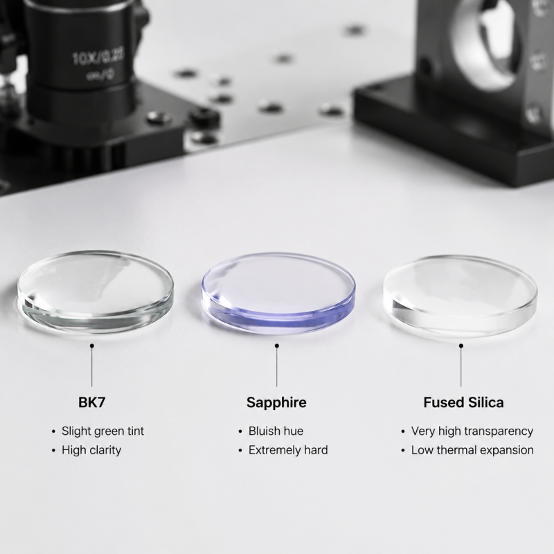
In contrast, spherical lenses, while lower in cost, often become the limiting factor in high-precision applications. In high-power scenarios, the material itself can matter even more than the shape. This is where LIDT (Laser Induced Damage Threshold) comes into play—the maximum laser energy density a material can withstand. Materials like fused silica, known for their excellent thermal stability and serious damage threshold, have become the default choice for high-power systems.
Coating is another factor that is often underestimated. An AR coating (anti-reflection coating) matched to the wavelength can boost transmittance to over 99.5%. However, if the wavelength range does not match, not only does efficiency drop, but additional reflections may be introduced, affecting system stability.
Where Designs Fail: Mechanical Reality and Stability
The performance of an optical system is determined not solely by design but by the combination of design and manufacturing. A typical issue is thermal drift. When a system runs for extended periods, materials undergo slight expansion due to temperature changes. This can shift the optical axis and disrupt the collimation state. Different materials behave differently—for example, stainless steel is more stable, while aluminum is lighter but expands more easily.
Another key point lies in the mechanical structure. Adjustable collimators are very useful in the experimental stage because they allow engineers to fine-tune the focus. However, in mass production environments, fixed structures are often more reliable because they reduce uncertainty.
In industrial settings, protection is also essential. Dust, contamination, or even airborne particles can create scattering sources on the lens surface, gradually degrading system performance. Therefore, sealed structures or protective windows are not optional add-ons—they are the foundation for long-term stability.
Conclusion
Selecting a fiber collimator is not about finding the best option in a spec sheet—it is about finding the “most suitable fit” within a system. The light source, propagation path, environmental conditions, and manufacturing capabilities all play a role in this decision.
A truly reliable approach is not simply comparing specifications, but clarifying the role of the beam in the system and then deducing the necessity of each parameter. For complex applications, rather than selecting components individually, it is often better to provide the spot requirements and operating conditions, allowing the design to be verified through simulation—this tends to yield results closer to real-world performance.
FAQ
Is a larger NA always better?
Not necessarily. A larger NA makes it easier to collect light, but also results in greater divergence. In systems requiring long-distance transmission or high collimation precision, a large NA may actually become a drawback.
Why does my beam look fine nearby but degrade over distance?
This is a typical divergence issue. What you are seeing is “local collimation,” not stability over distance. As the distance increases, divergence gradually becomes apparent. This is a physical limitation, not a component failure.
Is FC/APC necessary for all systems?
Not for all systems, but in high-power applications or those sensitive to stability, it significantly reduces back reflection and is well worth considering.
Can I just choose a high-end lens to solve everything?
No. The lens is only one part of the system. If the fiber parameters, alignment accuracy, or mechanical structure do not match, even the best lens cannot compensate for overall errors.
When should I use an adjustable collimator?
During R&D or debugging, it offers flexibility. But once in mass production, a fixed structure is usually more reliable because it reduces variables.