A cylindrical lens is a specialized optical component designed for unidirectional beam modulation. Its defining characteristic is that it possesses optical power along only a single axis, which causes it to focus or diverge light into a line focus rather than a conventional point focus. This unique capacity for uniaxial beam control grants it a critical and distinct positioning within optical system architectures.
Simply put, whenever an application requires altering the height or width of a beam without affecting its orthogonal dimensions, a cylindrical lens is the definitive solution. It allows light to be precisely reshaped along one specific axis while leaving the cross-axis entirely unchanged. With the rapid evolution of industries such as LiDAR, precision metrology, and high-resolution imaging, this engineering demand has become increasingly widespread. In the vast majority of these scenarios, the cylindrical lens acts as the core component governing critical benchmarks such as system resolution, beam uniformity, and long-term optical stability.

What Is a Cylinder Lens?
The fundamental nature of a cylindrical lens resides in its single-axis optical activity. This enables it to selectively modify the propagation state of a beam in one dimension without introducing any optical deviations in the orthogonal direction. Due to this cross-sectional asymmetry, light passing through the element undergoes compression or elongation along one axis instead of being forced into a single point, ultimately creating a linear focal distribution.
Uniaxial Beam Modulation Mechanisms
When light travels through a cylinder lens, the wavefront is effectively decoupled into two independent dimensions: one dimension undergoes refraction, where the light rays are spatially redistributed, while the orthogonal dimension maintains its native propagation state, bypassing the focusing cycle entirely. This segmented, direction-specific routing allows engineers to adjust the localized geometry of a beam without altering its macroeconomic propagation profile.
The breakthrough of this design is that it shatters the geometric constraints of conventional symmetric imaging systems, where both dimensions are forced to scale in tandem. This unlocking of geometric symmetry allows for much finer-grained control over the beam profile.
Design Freedom Unlocked by Uniaxial Control
In practical optical design, this capacity for single-axis modulation yields a significantly higher budget of freedom. System designers can alter an isolated dimension of the beam—such as expanding its width, compressing its profile height, or executing localized aberration correction—without disrupting the broader imaging matrix. This decoupled optimization allows each orthogonal axis to be tailored independently, yielding a beam profile that closely approaches the theoretical ideal.
Critical Importance in High-Precision Systems
As high-precision optical deployment advances, industrial demands for beam uniformity, symmetry, and environmental stability have grown exceptionally stringent. Uniaxial modulation allows a system to execute targeted optimizations on the beam profile without compounding the structural complexity of the optical train. From an engineering standpoint, its value lies in introducing a highly controllable directional degree of freedom, thereby expanding the flexibility and design envelope of the entire optical architecture.
The Working Principle of Cylindrical Lenses
The physical reason why a cylinder lens operates exclusively in one dimension is that its surface curvature is restricted to a single axis. That is to say, it possesses a refractive profile similar to a spherical lens along one vector, while remaining completely flat or devoid of curvature variations along the vertical vector. As a result, it exerts near-zero convergence or divergence on light travelling across that planar axis.

When a collimated beam enters a cylindrical lens, the wavefront can be modeled as two orthogonal components: the component aligned with the curved axis undergoes refractive path bending due to index transitions, leading to convergence or divergence. Meanwhile, the component aligned with the uncurved axis encounters no geometric gradients, and its propagation path remains essentially linear. Consequently, the beam is spatially redistributed along one axis while remaining undisturbed along the other.
It is precisely this structural profile—where optical power is generated in only one dimension—that prevents the output light from converging into a point focus, forcing it instead to compress or stretch into a precise line focus.
Engineering Advantages of Uniaxial Beam Control
In real-world system design, not every application requires simultaneous dual-axis modification of a beam. For example, a project may only require controlling the vertical profile of a beam or expanding its horizontal scanning width. Cylindrical lenses deliver this directional decoupling, enabling engineers to isolate and optimize a single dimension without interfering with the cross-axis optical behavior.
The direct advantages derived from this capability include:
- Precision Beam Shaping: Enables ultra-accurate tuning of focal spot height, width, and spatial uniformity.
- Expanded Degrees of Freedom: Allows independent optimization of optical parameters for different orthogonal axes.
- Enhanced Imaging and Scanning Fidelity: Minimizes residual astigmatism and non-ideal spot geometries that degrade system throughput.
- Streamlined Optical Configurations: Bypasses the need for complex, multi-dimensional elements to achieve localized beam optimization.
This uniaxial modulation capability sets the upper limit of optical performance in high-precision lasers, industrial machine vision, beam profile sculpting, and line-illumination systems, making it an irreplaceable tool in modern optical engineering.
The Challenge of Clocking (Rotational) Errors
In high-precision optical alignment, the axial alignment—frequently referred to as clocking—of a cylinder lens represents a critical factor governing system performance, often surpassing focal length tolerances or bulk material parameters in sensitivity. Because the optical structure of the lens is asymmetric, an axial misalignment of even 0.1 degrees can trigger severe degradation across the entire system.

Physical Consequences of Clocking Errors
- Inducement of Residual Astigmatism: The beam profile misaligns with the intended curved axis of the lens. This causes the focal positions of the two orthogonal axes to interlock, reintroducing parasitic astigmatism into the system.
- Degradation of Beam Quality (M2 factor): The resulting line focus loses its linear uniformity. The spatial energy distribution distorts away from the idealized profile, directly undermining transmission efficiency and metrological accuracy.
- Line Profile Tilt and Smearing: Especially inside line-scanning vision systems or sheet illumination networks, a clocking error causes the projected line source to warp, tilt, or exhibit geometric curvature across the target plane, severely reducing system uniformity and spatial resolution.
Engineering Mitigation Strategies
To isolate and minimize the impact of clocking errors on system performance, engineering teams deploy several structural control metrics:
- Mechanical Keying and Indexing Features: Integrating specialized orientation slots, flats, or alignment pins directly onto the lens substrate or cell housing ensures that the component automatically locks into correct axial alignment during hardware assembly.
- Sub-Degree Rotational Adjustment Mechanisms: Integrating high-precision, fine-thread mount sub-assemblies allows technicians to execute sub-degree rotational calibration during the active optical tuning phase.
- Metrology and Wavefront Verification: Leveraging optical interferometers or laser profiling alignment stations allows real-time validation of beam linearity and M2 factors, ensuring compliance with the system design budget.
Key Engineering Insight
Clocking errors represent one of the most common bottlenecks where theoretical optical design diverges from actual hardware performance. Even if a design is mathematically perfect, ignoring axial rotational tolerances will result in beam-shaping failure, non-uniform energy distribution, and uncorrected residual astigmatism. In high-performance configurations, taming the clocking error budget is frequently far more critical than selecting the base focal length itself.
Understanding the Primary Classifications of Cylindrical Lenses
Foundational Geometric Classifications
The baseline architectures of cylinder lenses are categorized by how they generate uniaxial optical power and manage monochromatic aberrations. These distinct structures represent unique wavefront-steering strategies rather than simple variations in physical shape.
- Plano-Convex Cylindrical Lenses: The most ubiquitous architecture utilized for single-axis focusing and laser line generation. They feature manufacturing simplicity and high optical throughput. However, under high numerical aperture (NA) configurations, they are prone to introducing single-axis spherical aberration, requiring careful optimization of the orientation of the curved face relative to the incident light to minimize wavefront errors.
- Plano-Concave Cylindrical Lenses: Engineered for single-axis divergence control, these components expand a beam or lower localized power density along one vector. They are common in the early expansion stages of anamorphic beam-shaping trains or galvo-scanning modules to set initial divergence constraints.
- Bi-Convex Cylindrical Lenses: Provide enhanced single-axis focusing power, enabling high linear energy densities within tight, short working distances. They introduce stricter demands for axial alignment and are highly sensitive to mounting tolerances.
- Bi-Concave Cylindrical Lenses: Primarily deployed for wide-angle single-axis divergence. They excel in systems requiring rapid spatial expansion of a line illumination profile, though maintaining uniform energy distribution across the outer periphery presents an engineering challenge.
- Meniscus Cylindrical Lenses: Utilizing a combination of positive and negative surface curvatures to execute real-time path compensation, these elements are engineered to minimize single-axis aberrations and enhance line focal uniformity, making them essential building blocks in premium line-source engines.
Core Structural Takeaway: The true difference among these geometries is not their focal length, but their unique capacity to manage single-axis wavefront errors.
High-Performance Cylinder Lens Architectures
When an optical system scales into high-precision regimes or must satisfy multi-parameter constraints, foundational monolithic shapes often fail to meet wavefront quality or multi-spectral requirements. This necessitates the introduction of advanced optical designs.
- Achromatic Cylindrical Lenses: By pairing distinct crown and flint glass substrates with complementary dispersion profiles, these doublet or triplet assemblies ensure that multiple wavelengths converge at an identical single-axis focal position. They are vital for multi-wavelength laser combinations or broadband illumination networks, eliminating color-induced line focal drift.
- Aspheric Cylindrical Lenses: Incorporating non-spherical mathematical coefficients across the single curved axis, these optics neutralize single-axis spherical aberration and high-order geometric defects under high-NA conditions. They yield exceptionally uniform line profiles with stable edge-energy distributions, making them the cornerstone components for achieving diffraction-limited line generation.
- Sphero-Cylindrical Lenses: Blending both spherical and cylindrical optical powers onto a single monolithic component, these hybrid optics execute simultaneous two-dimensional imaging and isolated single-axis modulation. They are frequently deployed to counteract complex asymmetric aberrations or inside highly space-constrained enclosures.
- Crossed Cylindrical Lenses: Configured by mounting two separate cylindrical lenses back-to-back with their curved axes oriented at 90 degrees, this setup allows completely independent tuning of the X and Y axes. It acts as a fully decoupled two-dimensional beam-shaping engine, widely utilized for circularizing highly elliptical laser profiles.
Ultimate Architectural Takeaway: The primary goal of high-end cylindrical structures is not to increase raw focusing power, but to provide precise control over single-axis wavefront degrees of freedom.
Substrate Material Selection and Engineering Boundaries
The ultimate performance limit of a cylinder lens is tightly coupled to its base material matrix. Substrate properties govern critical performance boundaries, including thermal lensing thresholds, laser-induced damage thresholds (LIDT), and chromatic dispersion behavior.
Substrate Material | Core Optical Characteristics | Primary Engineering Advantages | Typical Systemic Constraints |
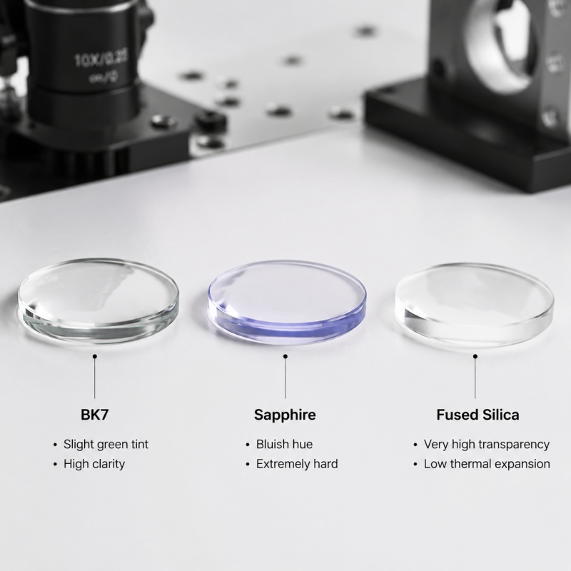
Fused Silica | Near-zero absorption, minimal thermal expansion, exceptionally high LIDT. | Outstanding wavefront stability under high-power loads. | Preferred for high-energy industrial lasers and precision UV metrology. |
N-BK7 (or equivalent) | Highly cost-effective, stable transmission across visible spectra. | Exceptional versatility and ease of manufacturing. | Standard for mainstream visible-spectrum industrial vision systems. |
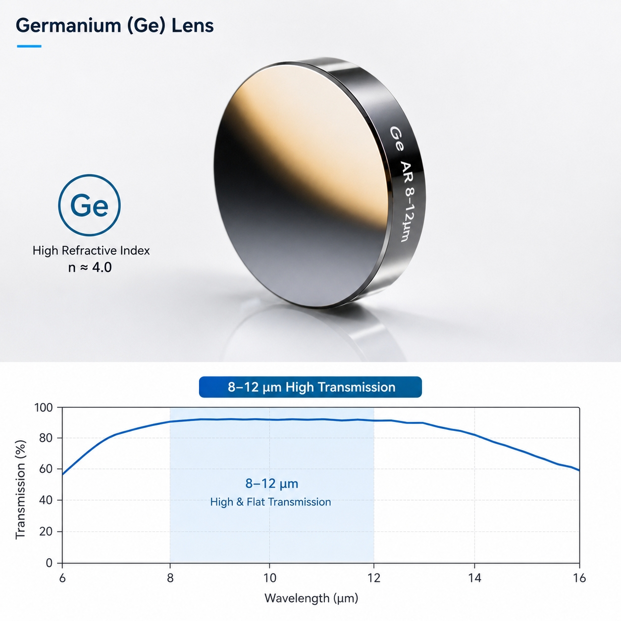
Zinc Selenide (ZnSe) | Elite infrared transmission window with minimal absorption. | The industry standard for high-power CO2 laser steering. | Restricted to IR and thermal imaging configurations. |
Calcium Fluoride (CaF2) | Ultra-low dispersion index, high broadband transmission from UV to IR. | Exceptional multi-wavelength focus consistency. | Sensitive to thermal shock and mechanical stress. |
Sapphire | Extreme mechanical hardness, high thermal conductivity. | Unmatched survivability in harsh, abrasive environments. | Highly challenging to grind and polish to sub-micron figures. |
Optical Plastics | Ultra-lightweight, high-volume repeatability via injection molding. | Lowest possible unit production cost at scale. | Limited to low-power consumer electronics; low thermal stability. |
Foundational Distinction: Cylindrical vs. Spherical Lenses
The root difference between a cylindrical lens and a spherical lens comes down to their active dimensions of optical power. A spherical lens maintains perfect rotational symmetry, applying identical optical power across both orthogonal axes (X and Y) simultaneously to focus or image a beam into a two-dimensional point. A cylinder lens deliberately breaks this rotational symmetry, confining its optical power to a single axis while treating the cross-axis as a transparent window, thereby enabling isolated, one-dimensional beam manipulation.
This structural divergence governs their functional division inside an optical train: spherical elements are tasked with establishing the global, symmetrical imaging baseline, while cylindrical elements are introduced specifically to break that two-dimensional symmetry, executing selective, axis-specific wavefront tailoring.
Real-World Case Study: Uniaxial Reshaping of Elliptical Laser Beams
Consider a standard semiconductor laser diode. Due to the physics of the edge-emitting cavity, it natively projects a highly asymmetric, elliptical beam profile with completely separate divergence profiles across its two orthogonal axes. For instance, a typical output configuration might feature a beam waist of 1.0 mm along the fast axis and 4.0 mm along the slow axis. If this raw elliptical output is directed straight into a standard optical train, it will trigger severe spot distortion, non-uniform energy distribution, and a massive drop in fiber-coupling efficiency.

If an engineer attempts to resolve this issue using only standard spherical lenses, the correction will fail. Because a spherical lens applies an identical scaling factor to both axes simultaneously, the aspect ratio of the ellipse remains locked, meaning the asymmetric profile cannot be circularized.
By introducing a pair of orthogonally oriented cylindrical lenses, the engineering team can decouple the two axes and manage them independently. The first cylindrical lens is aligned to manipulate only the fast axis, expanding or compressing its profile until its dimensions match the slow axis. The second cylinder lens is positioned further down the train to fine-tune the cross-axis collimation and ensure perfect beam-size matching. The result is a highly uniform, symmetric beam measuring approximately 4.0 mm by 4.0 mm.
The physics driving this process is decoupled control—defining unique optical trajectories for each axis independently rather than enforcing a blanket, two-dimensional transformation. This single-axis adjustment capability represents the primary engineering value that separates cylindrical lenses from spherical optics.
Architectural Deployment Logic of Cylindrical Lenses
When building an optical train, selecting a cylindrical lens should be driven by functional system requirements rather than product catalog categorization:
- Isolated Single-Axis Sculpting Needs -> Laser line projection, structured-light sheet illumination.
- Asymmetric Beam Correction Needs -> Circularizing elliptical diode outputs, energy profile homogenization.
- Wavefront Aberration Compensation -> Correcting targeted system-level astigmatism.
- Linear Sensor Integration -> Optimizing beam coupling into spectrometers and linear photodiode arrays.
- Wide-Area Linear Scanning -> Designing illumination channels for high-speed industrial conveyor inspection.
Core Architectural Logic: Whenever an optical system imposes different performance metrics on the horizontal and vertical vectors of a beam, a cylinder lens is almost always the optimal solution.
Key Specification Parameters for Component Selection
In practical system integration, specifying a cylindrical lens requires balancing several interlinked parameters rather than focusing solely on focal length:
- EFL (Effective Focal Length): Establishes the geometric track length of the system and the spatial positioning of the line focus. It serves as the baseline matching parameter.
- Fan Angle: Dictates the total length of the projected line source and the total spatial coverage across the target scanning plane; a critical constraint in sensor coverage design.
- Wedge (Total Indicated Runout): Introduces unintended angular deviations into the beam path. In high-precision setups, wedge errors can degrade performance faster than native surface aberrations.
- Axis Tilt: Directly deforms the single-axis symmetry of the optic, acting as a common hidden cause behind line bowing, spot smearing, and system resolution loss.
- Thin-Film Coating and Spectral Matching: Governs total insertion loss and ensures multi-wavelength transmission consistency. This specification is highly critical for preventing thermal lensing inside high-power industrial laser heads.
Summary
The primary value of a cylindrical lens does not lie in architectural complexity or multi-functional versatility; it lies in its elegant capacity to provide independent, single-axis control over a wavefront. By applying precise optical modulation along one designated vector while remaining passive along the orthogonal axis, it decouples the directional behavior of a beam. This makes it an irreplaceable component in any optical architecture that requires separate management of horizontal and vertical profiles.
From an engineering perspective, this utility delivers three core capabilities: the precise shaping of single-axis beam profiles, the systemic elimination of astigmatism and asymmetric optical defects, and the highly granular control of total wavefront degrees of freedom.
FAQ
Q1: What is the biggest difference between a cylindrical lens and a spherical lens?
A cylindrical lens refracts light in only one direction, forming a line focus. A spherical lens refracts light in both axes simultaneously, forming a point focus.
Q2: What are cylindrical lenses mainly used for?
They are commonly used in astigmatism correction, laser line generation, beam shaping, line scanning, spectral analysis, and industrial inspection systems.
Q3: Can cylindrical lenses be used in laser systems?
Yes, and they are often indispensable in laser beam shaping, particularly for correcting elliptical beams and generating line-shaped light sources.
Q4: What are the most important parameters when selecting a cylindrical lens?
Key parameters include Effective Focal Length (EFL), material, wedge angle, center thickness deviation, divergence angle, and spectral band matching.
Q5: Can cylindrical lenses reduce optical aberrations?
Basic cylindrical lenses do not inherently eliminate aberrations. However, designs incorporating aspheric surfaces or achromatic structures can significantly improve system aberration performance.