In traditional optical design, lenses are almost synonymous with “curved surfaces.” Through spherical or aspherical structures, light is refracted at the interface to achieve focusing, imaging, or collimation. However, as optical systems continue to evolve toward miniaturization, modularization, and high integration, solutions relying solely on curved surfaces are revealing significant limitations: increased system length, a higher number of components, and greater alignment and adjustment difficulties.
Against this backdrop, G-Lens (GRIN Lens, Gradient-Index Lens) has gradually become a key component in micro-optical systems. Unlike conventional lenses, G-Lens does not emphasize “surface curvature” but shifts the core of optical design to the interior of the material, guiding light propagation through a continuous variation in refractive index. This approach fundamentally changes our intuitive understanding of lenses.
What is G-Lens (GRIN Lens)?
G-Lens, short for Gradient Index Lens, is essentially characterized by a refractive index that is not constant but varies spatially. In most GRIN lenses, the refractive index is distributed radially:
- It is highest at the optical axis center.
- It gradually decreases toward the edges.
- The refractive index variation is continuous and controllable.

This structure means that light entering a G-Lens does not travel in a straight line as it would in ordinary glass. Instead, due to the persistent refractive index gradient, it is “continuously pulled back” toward the optical axis. Functionally, a G-Lens is essentially an optical device that accumulates numerous tiny refractions.
How G-Lens Works:
How Is Light “Bent” Inside the Material?
In a homogeneous medium, light travels in a straight line. In a medium with a refractive index gradient, light continuously bends toward regions of higher refractive index.
In typical GRIN lens designs, the refractive index distribution is often approximated by a parabolic form. This distribution causes light to follow a trajectory similar to simple harmonic oscillation in the radial direction—light neither diverges indefinitely nor focuses all at once. Instead, it periodically approaches and moves away from the optical axis within the lens.

The Engineering Significance of Pitch
To quantify this propagation behavior, the concept of Pitch is introduced. Pitch describes the proportion of a complete oscillatory cycle that light undergoes inside a GRIN lens. Different Pitch values correspond to different functions:
- 1/4 Pitch: Converts divergent light from a point source or fiber output into collimated light, the most common form in fiber-optic communications.
- 1/2 Pitch: Achieves inverted imaging, often used in image transmission systems.
- Non-integer Pitch: Used for special focusing distances or custom beam-shaping requirements.
In practical engineering, the choice of Pitch directly determines the role of the G-Lens in the system.
Why Does G-Lens Rely on Special Materials?
The ability of G-Lens to achieve focusing or collimation without curved surfaces is not because “any material can be processed into a GRIN structure.” Instead, it depends on the combined effect of specific material systems and manufacturing processes. Essentially, the core of G-Lens lies not in its “shape” but in the controllable distribution of the refractive index within the material.
Where Does the Refractive Index Gradient Come From?
In ordinary optical glass, the material composition is uniform, and the refractive index remains constant throughout the volume. Regardless of the shape into which such materials are processed, light travels in straight lines inside them, and optical path changes rely solely on surface curvature. The materials used in G-Lens are entirely different. In GRIN materials, the refractive index gradient is typically achieved through:
- Multicomponent glass or polymer systems: The material consists of multiple chemical components, each with a different refractive index.
- Radial or axial composition distribution control: During manufacturing, the concentration of high-refractive-index components is made higher in the central region and gradually decreases outward, forming a continuous refractive index variation.
- Ion exchange or diffusion processes: By controlling the depth and distribution of ion diffusion within the material, a stable and predictable refractive index gradient is achieved.
The result is not a “layered structure” but an optically continuous refractive index function, which is a prerequisite for the proper operation of a GRIN Lens.
Common G-Lens Material Systems
From an engineering application perspective, the types of materials suitable for G-Lens are limited, primarily including:
- Gradient-index glass (GRIN Glass): One of the most mature and stable material systems, characterized by stable refractive index distribution, good adaptability to operational environments, and suitability for fiber-optic communications and precision optical systems. Such materials are typically prepared through ion diffusion or melt-controlled processes, requiring highly precise process windows.
- Gradient-index polymer (Polymer GRIN): Often used in medical imaging and disposable or lightweight optical probes. Its advantages include flexible processing, relatively low material costs, and the ability to achieve complex designs. However, it generally lags behind glass systems in terms of temperature stability and long-term reliability.
Why Can’t Ordinary Optical Glass Serve as a Substitute?
This is a crucial and often misunderstood engineering issue. Not all optical glass can be “made into” a G-Lens, for three main reasons:
- Limitations of compositional uniformity: Conventional optical glass aims for compositional uniformity, whereas GRIN Lens requires “non-uniform but controllable” composition.
- Non-adjustable refractive index: Even with heat treatment or mechanical processing, the refractive index of ordinary glass remains constant, unable to form a continuous gradient.
- Process irreversibility: The refractive index gradient must be introduced during the material forming stage; it cannot be achieved through polishing or cutting afterward.
Therefore, G-Lens design must be deeply integrated with the material system from the outset, not merely a matter of optical shape design.
Material Category | Material Examples | Wavelength / Application | Manufacturing Method | Typical Uses |
Optical Glass | Aluminosilicate glass (ion-exchanged Ag⁺/Li⁺) | Visible / Near-infrared | Ion exchange method | Fiber coupling, precision optical modules |
Polymer | PMMA, PC | Visible / Near-infrared (low-power, low-cost) | Partial polymerization / UV curing | Medical endoscopes, low-cost optical modules |
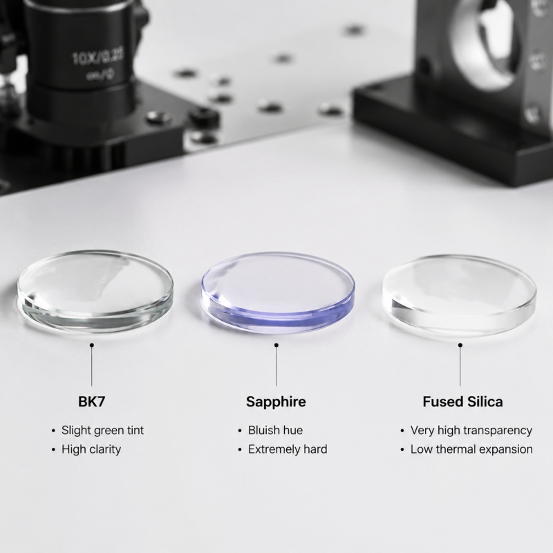
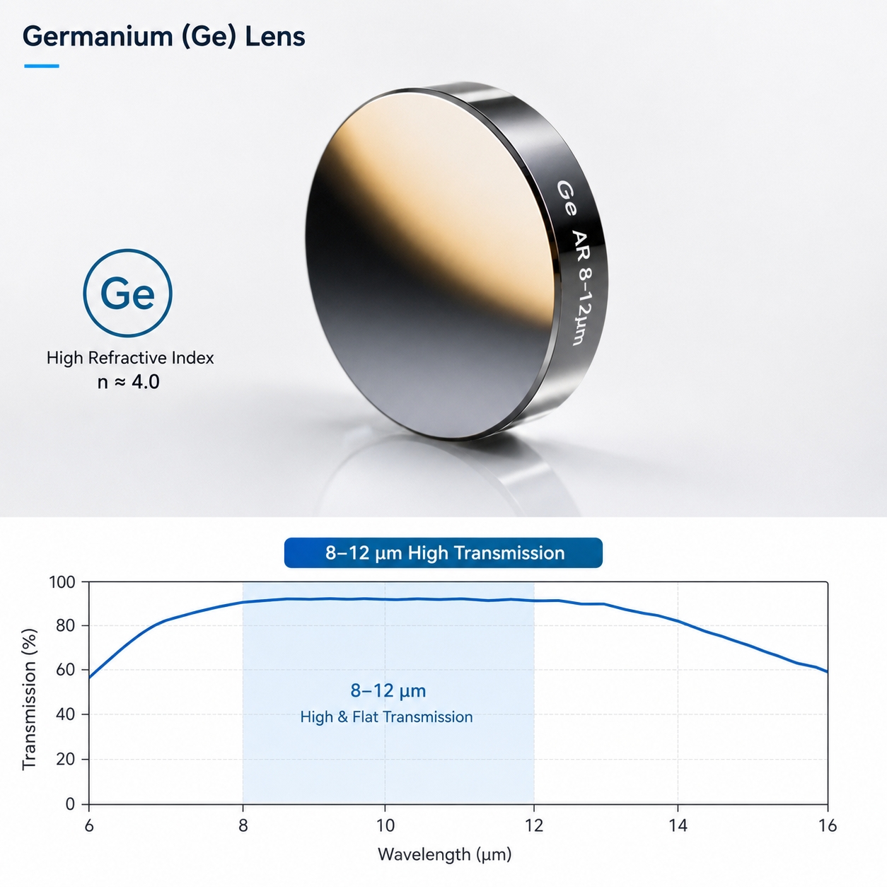
Infrared Materials | Ge, ZnSe, Si, Sapphire, Fluorides | Mid-wave / Far-infrared | Chemical vapor deposition / Melt processing | Infrared imaging, sensors, ranging modules |
Structural Forms and Common Types of G-Lens
Structurally, G-Lenses are mostly rod-shaped cylindrical structures, often with flat or slightly treated end faces. This design is inherently well-suited for axisymmetric systems. Common types include:
- Rod GRIN Lens: The most widely used form, particularly suitable for fiber-to-fiber coupling, fiber-to-free-space collimation, and micro-optical modules. Its advantages include small size and tolerance-friendly axial alignment.
- GRIN Imaging Lens: Mainly used for short-distance image transmission, such as in endoscopes and micro-inspection systems. These lenses emphasize image transfer capability rather than high numerical aperture.
- GRIN Collimating Lens: Typically placed at the light source or fiber output to obtain a stable, compact parallel beam, widely used in laser diode systems.
The Fundamental Differences Between G-Lens and Conventional Lenses
From the perspective of “where light is bent,” the differences are clear:
Comparison Dimension | Conventional Lens | G-Lens |
Light Control Method | Surface refraction | Internal refractive index gradient |
System Length | Relatively long | Very short |
Number of Components | Often requires multiple elements | Single element sufficient |
Alignment Difficulty | Relatively high | Easier axial alignment |
Because of these differences, G-Lens is not an “upgraded version” of conventional lenses but an alternative solution tailored to specific system configurations.
Engineering Advantages of G-Lens
In practical applications, the advantages of G-Lens are mainly evident at the system level:
- Extremely high spatial efficiency: Can achieve collimation or imaging within a few millimeters.
- System simplification: Reduces the number of lens elements, lowering tolerance accumulation risks.
- Excellent axis symmetry: Ideal for direct coupling with fibers and lasers.
- Modular-friendly: Easily integrated into standard optical modules.
These advantages make G-Lens particularly prominent in applications where “space is more critical than performance.”
Limitations and Design Boundaries of G-Lens
From an engineering perspective, G-Lens is not a universal solution. Its performance is constrained by factors such as the wavelength dependence of the material’s refractive index gradient, limited numerical aperture, thermal effects, and material damage risks under high-power laser irradiation, and the precision of refractive index distribution processing. Therefore, G-Lens is more suitable for optical systems with well-defined functions, clear wavelength bands, and compact structures. These engineering constraints must be comprehensively evaluated during design to ensure reliable performance.
Typical Application Scenarios for G-Lens
Based on the above characteristics, G-Lens is widely used in:
- Collimation and coupling in fiber-optic communications
- Medical endoscopy and micro-imaging systems
- Laser ranging and sensing modules
- Compact optical paths in machine vision
- Micro-probes and integrated optical components
In these fields, G-Lens is often the key device enabling “small yet stable” performance.
How to Properly Select G-Lens in Engineering?
- Target Function: Clearly define whether the application requires collimation, imaging, or focusing. Different functions correspond to different refractive index distributions and geometric designs, directly affecting the beam propagation path and system performance.
- Pitch and Working Distance Matching: The lens’s oscillation cycle (Pitch) determines the propagation state of light inside the lens. The appropriate Pitch must be selected based on the system’s working distance to ensure effective collimation or imaging.
- Numerical Aperture (NA): NA determines the beam divergence angle, light throughput, and imaging resolution. Ensure the lens NA meets the system’s optical performance requirements.
- Operating Wavelength and Material Compatibility: The refractive index gradient of different materials is wavelength-sensitive. Choosing an incompatible material may lead to dispersion, reduced efficiency, or wavefront distortion.
- Standard Components vs. Custom Design: For mature, conventional solutions, standard GRIN Lens components can quickly meet design needs. High-performance or specialized systems often require custom lens length, Pitch, NA, or materials to precisely meet specifications.
Conclusion
The value of G-Lens lies not in “replacing all lenses” but in providing optical engineering with a solution path distinct from curved-surface design. When system space is constrained, structures require high integration, and optical paths must be stable and controllable, a GRIN Lens can often accomplish tasks that are difficult for conventional lenses with an extremely simple structure.
If your optical system is moving toward miniaturization, understanding and appropriately applying G-Lens can often lead to dual optimization in both structure and performance.